30 May 2023
Capillary GC Column Manufacture. A Troubleshooting Insight.
By Tony Taylor
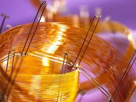
After having recently written about how to kill your GC column [1], I wanted to ‘flip’ the situation and explain a little about how Wall Coated Open Tubular (WCOT) capillary GC columns are manufactured. Figure shows a typical cross section of a WCOT column, showing the fused silica tubing with its polyimide coating and internally coated film of stationary phase.

Figure 1: Cross section of a modern WCOT capillary Gas Chromatography column
I’ve always believed that an insight into the manufacture of the columns we use daily for GC applications, leads to a deeper understanding of analytical problems as they occur.
1. Fused Silica Tubing manufacture
2. Winding onto column cage
3. Tubing preparation
4. Tubing leaching
5. Tubing Deactivation
6. Filling with dissolved stationary phase or monomers
7. Coating
8. Crosslinking
9. Rinsing
10. Curing
11. Special treatments
12. Curing
13. Quality control testing
The length of the list indicates just how complex the GC column manufacture can be, steps 2 to 13 alone typically take between 10 and 12 days to complete.
Let’s look at the some of the steps in more detail and explore possible implications to problems with the column in use and pick up some troubleshooting hints related to the manufacture of the worlds most used chromatography columns.
Fused Silica Tubing Manufacture
Figure 2 shows a typical manufacturing process for the slow draw / low tension process of fused silica capillaries. It should be noted that an even more complex process is used for fast draw / high tension processes.
Synthetic fused silica rods are fed into a 2000oC graphite furnace (often 10m above the production floor) which is gas shielded. The silica melts under precise heating conditions and is ‘drawn’ by a capstan, which is many meters away on the factory floor. The drawing speed and tension are very closely controlled as these parameters dictate the uniformity of the outer and inner diameter of the tubing. These parameters are also closely monitored by laser micrometers positioned within the drawing rig, which are connected to the capstan so that draw speed may be adjusted in order to maintain the capillary diameter within specification tolerance. Available data shows that silica capillary manufacturers can control to within around 4% of the nominal internal diameter, which for a 0.53mm capillary would be 0.508 mm - 0.554mm. This may not seem significant but equates to approximately a 10% variation in the optimum linear carrier gas velocity or 20% in column volume for capillaries of nominally the same length.
Along the drawing path, several coating baths apply successive layers of polyamic acid solution which are subsequently cured to build the yellow/brown outer coating we are all familiar with, which imparts mechanical strength, protection from abrasive damage and flexibility to the capillary. A single ‘draw’ operation can produce as much as 15km of capillary with 0.25mm internal diameter at speeds between 3 and 40m per minute.
Improper or poorly cured polyimide layers can lead to issues with the quality of column cuts. Under-cured polyimide is relatively soft and does not yield easily to most tools used for cutting capillary columns. Clean cuts (defined as cuts at approximately 90° to the column axis with only minor protrusions or voids of glass or polymer and no silica chip formation) are quite difficult to achieve with poorly cured polyimides. Such ‘ragged’ column cuts can lead to issues such as peak tailing and/or splitting and chips of silica falling inside the column can lead to irreparable damage of the stationary phase and usually results is exposure of the underlying silica which typically will give tailing peaks with more polar analytes.

Figure 2: Schematic diagram of the low-tension silica drawing and coating process (Reproduced with permission from reference 2)
To reduce the level of surface activity within the drawn capillary tubing, it is possible to complete the drawing process with the inner surface of the capillary under an inert gas atmosphere, which reduces the level of acids of nitrogen forming on the inner surface, which, when combined with an residual or atmospheric water, will hydrolyse the silica to active silanol groups (Figure 3). Controlling the level and homogeneity of any residual surface silanol species is important for the next phase of capillary column production.
The leaching process typically involves an acid wash which can help to remove impurities such as chlorine, acids of nitrogen and other sources of catalytic activity such as metal ions, all of which can ultimately give rise to active sites which will cause peak tailing with more polar analytes.
Next the inner surface is hydrolysed to maximise the concentration of surface silanol species. Whilst this may seem counter intuitive, as silanol species cause peak tailing with polar analytes, it does ensure that further hydrolysis post stationary phase deposition is less likely and that the silanol concentration is normalised from batch to batch.

Figure 3: Various impurities and the formation of surface silanol species via hydrolysis on the inner silica surface of the drawn capillary. (Reproduced with permission from reference 2)
Leaching and Deactivation
The next stage in the production process is to block or deactivate the surface silanol species using purified and well characterised reagents. Impurities in the deactivation reagent may lead to problems with the column coating and changes in the composition of the deactivation reagent(s) can lead to batch-to-batch variation in the stationary phase bleed profile. Reagents such as organochlorosilanes, alkoxysilanes, hexamethyldisilazine, or other reactive compounds are used for the chemical deactivation process. The reagents and reaction conditions used tend to be proprietary to manufacturers, and the variation in deactivation chemistry are often responsible for the differences in column performance between manufacturers. Deactivation chemistry can also be ‘tuned’ for various classes of problematic analyte and the resulting phases are designated as ‘optimised’ for a named application.
Finally in this stage of production, further treatments may be added to optimise the ‘wetability’ of the surface to less polar or more polar stationary phase polymers. This helps to ensure a uniform stationary phase deposition and hence optimised column efficiency. The column is then washed with a pure solvent and dried under an inert atmosphere.
Coating, Crosslinking and Curing
The next stage in the process is coating and crosslinking, which is critical to ensure good chromatographic resolution and reproducibility. It is important to carefully control phase (film) thickness and homogeneity and most modern columns are crosslinked to bind them tightly to the inner wall of the column, adding thermal stability, lowering activity and giving the ability to solvent wash the column if required.
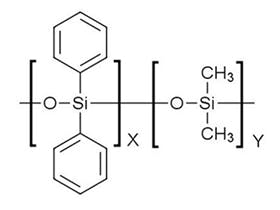
The purity and chemistry of the polymer used to coat the column is of upmost importance and good manufacturers will synthesise, purify and test the polymers in-house prior to coating to ensure quality and reproducibility. Small variations in the ratio of the monomers within the polymer can cause large relative retention shifts, so manufacturers will check each batch of polymer using the retention indices of test mixes. They may also remove lower molecular weight fractions of the polymer to reduce column bleed to acceptable levels. Again, column bleed may be tested on a small number of column columns prior to the polymer batch being accepted for large scale manufacture.
Once the polymer has been demonstrated to be fit for purpose, it is dissolved in a suitable (usually proprietary and optimised) solvent mix at a concentration which will ultimately determine the stationary phase film thickness.
Most modern WCOT capillary GC columns are coated using a ‘static coating’ process in which the entire column is filled with the stationary phase solution, one end carefully sealed and the other end connected to a vacuum pump. The column is held at a constant and optimised temperature, typically using a water bath, and the volatile solvent evaporates back towards to the plugged end of the column (Figure 4).

Figure 4: Static Coating process of WCOT capillary columns (Reproduced with permission from reference 3)
The level of vacuum applied and the temperature must be precisely controlled to achieve the correct rate of evaporation of the solvent in order to avoid ‘bumping’ of the stationary phase, which results in a non-homogenous deposition of the stationary phase and poor efficiency. The temperature of the column is typically controlled via immersion into a water batch which is shown in Figure 5. A ‘bumped’ GC stationary phase is shown in Figure 6 where ‘gaps’ or ‘bubbles’ within the stationary phase can be seen as the lighter regions highlighted in the figure.

Figure 5: GC columns being coated in a water batch to carefully control the column temperature.

Figure 6: GC column showing areas of stationary phase inhomogeneity due to ‘bumping’ of the phase caused by issues with the temperature or evaporation rate of the solvent during coating.
For columns which require higher thermal stability, the polymeric molecular weight and degree of crosslinking need to be considerably higher and the polymer has gum like physical properties and consequently the production of a useable ‘solution’ of the polymer may not be possible. In this case, oligomers (or other precursors of the final polymer) and polymerisation initiators are coated onto the capillary wall. The polymerisation reaction can then be carried out in-situ either before or after the solvent evaporation, in an oxygen free environment. These ‘crosslinking’ processes are highly proprietary as they are, in part, responsible for the thermal and chemical stability of the stationary phase effectively immobilising the coated polymer onto the inner wall of the capillary column. These processes are the ‘secret sauce’ of the column manufacturer and almost nothing is available online or in patents regarding crosslinking or immobilisation chemistry.
As mentioned above, when using the static coating technique, the film thickness of the stationary phase is controlled using the concentration of the polymer or monomers/oligomers used to coat the inner wall of the capillary. The phase ratio (b) of the column is the ratio of the volume of stationary phase to the amount of carrier gas within the capillary and this is a critical parameter to ensure reproducible analyte retention time from batch to batch of columns.

Equation 1.
Vm is the volume of mobile phase, Vs is the volume of the stationary phase, r is the radius in micrometers, and df is the stationary phase film thickness.
This goes some way to explain why the variations in capillary inner diameter are so important and any unexpected variance in the column inner diameter (2d in equation 1) may cause variation in the phase ratio if the polymer concentration, and therefore the film thickness, used to coat the column is constant. Therefore, to avoid batch to batch variability, manufacturers may measure the external and internal diameter of the capillary column and make small adjustments to the polymer concentration to maintain a constant phase ratio on a batch-to-batch basis. This should ensure that the pressure applied by the electronic pressure control until of the GC does not have to be altered to obtain the same analyte retention time after changing to a new column of the same stationary phase and physical dimensions. However, no matter how diligent the manufacturer, it is almost impossible to obtain an exact phase ratio throughout the entire length of the capillary column – that is, the ratio of column internal diameter to coating film thickness may subtly vary along the length of the column. This is the reason why, if one cuts a 60m GC column exactly in half, retention times from each of the two resulting 30m columns may vary!
Following the application of the stationary phase and any crosslinking, any unreacted polymer or impurities are removed from column through solvent rising with appropriate solvents.
After drying in an inert atmosphere the column may be heated (cured) prior to any final ‘special treatments’ which are primarily chemical modifications of the stationary phase or underlying silica surface. These treatments may, again, modify the stationary phase to perform particularly well with particular analyte classes. The modification chemistry may be carried out using gas phase or vapour deposition techniques.
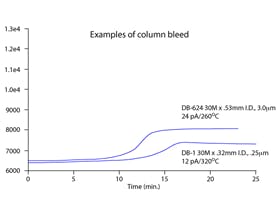
The column is then heated (cured) by gently raising the column temperature in an oven containing an inert gas, up to it’s maximum operating temperature. This will expel any remaining by-products and impurities from the column but this ‘bleed’ will quickly reduce to a level which represents the bleed profile of the new column. It should be noted that all WCOT GC column bleed all of the time, but these modern manufacturing techniques and treatments ensure that we have extremely low levels of underlying bleed for our analyses. The columns will continue to produce low levels of bleed if we are diligent in excluding oxygen, moisture and contaminants from the column during routine use, typically by using high quality carrier gas and using gas filters.
QC Testing
Finally, the columns are QC tested by manufacturers who choose test mixes which contain analytes to act as probes for the phase chemistry under test or the specific application for which the column will be used. The probes are typically chosen to highlight any issues with retention, selectivity, efficiency and peak shape, exploring the phase chemistry, phase ratio, phase bleed and the deactivation chemistry of the stationary phase. Some manufacturers will test each individual column whilst others may test only a selection of columns from a particular batch. Typically, the test chromatograms will be obtained under isothermal conditions which tend to reveal more about test probe peak shape and efficiency than temperature programmed operation, where peaks are sharpened due to thermal focussing and lower column residence times. Manufacturers will have their own internal test specifications which may be more stringent than the specifications provided within their sales literature.
I hope that this has given you some insights into the complexity of GC column manufacture and the care which manufacturers take to produce a column which will perform to our exacting standards, out of the box. I hope also that this information helps with your future troubleshooting efforts.

Tony Taylor, Chief Scientific Officer, Element Life Sciences (EMEAA)
Tony has worked as a chromatographer in the Pharmaceutical, Polymer, Contract Analysis and Consulting Industries for more than 35 years. His experience includes; HPLC and GC method development, development and troubleshooting of LC-MS and GC-MS methods, HPLC stationary phase characterisation, targeted and untargeted trace analysis, GC-MS spectral interpretation, solid phase extraction and development of sample preparation methods. Tony is a founder of CHROMacademy and has delivered training in chromatographic analysis to thousands of students globally.
References
[2] Fused-Silica Capillary. The Story behind the Technology, Steve Griffin, LCGC North America Volume 20, Number 10, October 2002
[3] The Art and Science of GC Capillary Column Production. Ron Majors, LCGC North America-07-01-2007, Volume 25, Issue 7, Pages: 616–631
Related articles