09 Feb 2021
GC Column Degradation
Our technical support and application chemists are often asked how long their GC columns should last. In the words of John F Kennedy, ‘Ask not what your column can do for you - ask what you can do for your column’. The original quote, of course, spoke about “country” but as you will see, it’s a very relevant premise!
Before we get on to answering this question, for which I will tell you there is no single correct answer, we should take a look at the anatomy of a column and it’s manufacture.
As most readers will probably know, the column ‘walls’ are made from silica tubing, typically coated in a strengthening outer coat (outside wall only) of polyimide, which ensure the silica doesn’t break upon flexing. The inner wall of the silica tubing is coated with the stationary phase, which is most cases will be a cross-linked polymer and sometimes this will be chemically attached (bonded) to the inner wall of the silica tubing. A typical GC column cross section is shown in Figure 1.
 capillary GC column.")
Figure 1: Typical cross section of a wall coated open tubular (WCOT) capillary GC column.
The silica tubing surface is populated with siloxane bridges and silanol species and the preparation of this surface prior to stationary phase coating critical. The siloxane species (Si-O-Si) are strained and can easily adsorb water from the atmosphere or from reagents used in column preparation and this needs to be very carefully controlled. Controlling the amount, and crucially the ‘type’, of surface hydroxyl features (-OH) from either silanol (Si-OH) or adsorbed water is critical in determining the level of chemical activity, bleed and stability of the resulting bonded GC column. Therefore, decades of development have gone into optimising the pre-treatment and deactivation steps which manufacturers employ prior to the application of the stationary phase. As mentioned above, the quality of reagents and the exclusion of water and other impurities such as residual metal ions, are vitally important when pre-treating and deactivating the bare silica inner surface. Surface treatments such as leaching, acid washing and the application of the deactivation reagent to block surface silanol species are typically different between manufacturers and will ultimately dictate the quality of the column, especially with respect to the peak shape obtained from polar and ionogenic analytes. The nature of the deactivation agent will also differ depending upon the stationary phase chemistry (primarily the polarity of the stationary phase to be applied) and is designed to be more ‘wettable’ to the stationary phase chemistry.
Most modern stationary phases are manufactured via a static coating method whereby a mixture of oligomers and polymeric initiators of the desired stationary phase polymer are filled into the column in solution under an oxygen free environment. The type and concentration of the oligomers in solution dictate the ultimate stationary phase chemistry and film thickness. The inlet end of the column is then sealed and a vacuum applied to the outlet end, whilst the column is held at a constant temperature. This causes the solvent to evaporate from outlet to inlet at a controlled rate which deposits the oligomeric species in a homogenous film along the whole column length. The column can then be heated, or catalysts introduced, which causes the deposited oligomeric species to polymerise in the presence of the initiators forming a polymeric film of uniform thickness on the inner wall of the column. Using this method, the polymer crosslinks not only to itself but with surface species on the silica inner-wall and these columns are said to be ‘immobilised’ and are more stable, showing inherently lower levels of stationary phase bleed. It should be noted that the polymerisation process can also be initiated in solution prior to the solvent evaporation step, however these stationary phases are non-immobilised (or ‘coated’) and therefore show lower inherent stability.
Any residual oligomers can then be solvent rinsed from the column and the residual rinsing solvent is removed from the column by slowly heating the column in an inert atmosphere.
The specific reagents, conditions and methods used are closely guarded secrets of manufacturers and very little is published in the literature or in patents about the specific reagents and methods used.
So now we know a little more about the column manufacturing process , lets look at what happens at the end of a column’s lifetime, specifically by defining what might constitute column ‘death’. From an analytical perspective, the results obtained from analyses or system suitability tests will probably show loss of efficiency (peak broadening), loss of resolution or a subtle change in selectivity, a degradation in peak shape (fronting, tailing or peak splitting) or an inability to distinguish low analyte concentrations from noise or bleed (loss of analytical sensitivity). Of course, these symptoms may be combined, and at some point we will need to consider replacing the column. No matter how much we trim the front of the column, we just can’t achieve acceptable chromatography or quantitative specification requirements.
So why do we get to this position, how do we decide to place a ‘do not resuscitate’ order on the column and what can be done to extend column lifetime under our typical operating environment? Well, as heralded earlier, there is really no single correct response and the column lifetime will ultimately depend on a number of factors including the type of GC column used, the application, the GC method and your treatment of the column during it’s lifetime. When I’m teaching a GC class, it’s usually at this point that I say, whilst a lot of what I’m about to write can be seen as ‘someone else’s issue to deal with’ and the cost of new column won’t be coming from your salary, we should also bear in mind that not being able to get on with work because the column you just installed is a ‘dud’ can be infuriating.
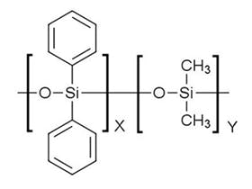
Perhaps the biggest issue facing even the best columns on the market is loss of stationary phase, which happens on an on-going basis, our job is to make sure that the rate of loss is a low as we can make it and for the bleed to be consistent. In the case of the polysiloxane based phases, the presence of oxygen catalyses the cleavage of backbone siloxane units that were formed during the stationary phase polymerisation process described above, via a ‘back biting’ reaction as shown in Figure 2. Whilst this reaction is catalysed at higher temperature, it also occurs at room temperature.

Figure 2: Reaction scheme for formation of cyclic polysiloxane bleed products from a dimethyl polysiloxane immobilised GC stationary phase.
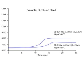
A classic stationary phase profile with increasing temperature is shown in Figure 3.

Figure 3: Typical capillary GC stationary phase bleed profile for two different polysiloxane based stationary phases (Figure reproduced with permission, Agilent Technologies, Santa Clara, Ca, USA).
On standing, the stationary phase will become oxidised and will bleed. Obviously one way to protect columns in storage is to cap them – column caps are recommended as opposed to septa! One should also note that the reaction in Figure 1 is also catalysed by UV light – which is why it’s a good idea to keep your capillary GC columns boxed between outings.
On column installation, it’s important to get rid of the bleed products formed during storage to ensure the lowest levels of baseline noise and baseline displacement during temperature programming. This is typically achieved using column conditioning, where the column temperature is elevated slightly above the required upper working temperature and left there for a period of time to drive off the volatile bleed products. It’s very important not to just install the GC column, whack the oven up to the isothermal or gradient temperature maximum stated by the manufacturer and leave it overnight. You are literally throwing precious stationary phase out into the detector!! And yes – you should be aware of the upper temperature limits for your columns and stick to them – the gradient temperature maximum (usually the higher of the two figures quoted on the column box or hanger tag) should not be used for more than a few minutes at a time.
For more specific information on column conditioning and how to do it, see this article: GC Column Conditioning – Stop Wasting Time and Money!
You will have noticed that the words oxygen and oxidation were used several times in the preceding discussion, generally because oxygen is the biggest GC stationary phase killer of all, and we need to ensure that we expose the column to the lowest amounts of oxygen possible on an ongoing basis. Yes folks, that means we need to pay attention to our friends the gas filters that are fitted (hopefully!!) to the gas line between the carrier source and our instrument. One of those traps, typically containing a metal catalyst, is there to remove oxygen and the best of them typically achieve O2 levels below 1ppb within the flowing carrier gas stream. You need to ensure, on an-ongoing basis, that the trap is not exhausted and that’s why I recommend the use of an indicating trap, typically containing a copper oxide indicator which turns from green to grey as the oxygen levels exiting the trap become too high.
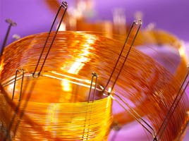
This is YOUR responsibility, don’t leave changing gas traps to someone else, otherwise the answer to the titular question will be, ‘longer than they do now because you don’t look after them properly’! Figure 4 shows a ‘combination’ gas filter which reduces levels of oxygen, moisture and hydrocarbon, but the important point to note is that a quick glance at the gas filters will tell you whether the oxygen filter tell-tale is green (good) or grey (bad). Come on folks – check your traps, it’s really not that difficult, and of course get a replacement trap into that gas line as quickly as possible if you discover that it’s exhausted. As a minimum gas filter checking should be part of your routine maintenance schedule but can also be included in method or instrument SOP’s as part of the acquisition set-up sections

Figure 4: A typical ‘combination’ gas filter, with the green ‘oxygen’ indicator clearly marked.
Combining these last two points together, extended exposure of the stationary phase to high levels of oxygen at high temperature is the GC column equivalent of a rock and roll lifestyle – i.e. they will die young!
I often get asked about the influence of water on GC stationary phases, both as an impurity in the carrier gas and as a solvent for injection. There is so much information out in the ether about this subject, I’ll just make a quick summary of the main points here. Most bonded phases have nothing to fear with regards to water exposure, the bonding process rendering the phase less susceptible to water damage. Coated phases are a different matter and water should be avoided with these phases and will significantly shorten the column lifetime. It should be noted however that any active sites within the phase can lead to water absorption, which can lead to some degree of irreproducibility in retention. Wax phases are more susceptible to this phenomenon (they are polyethyele glycol (PEG) based) and the more water that is adsorbed, the more irreproducible they will become in terms of both retention and selectivity. It should be said that most manufacturers have developed wax phases which are more water compatible.
Moisture traps are also typically fitted to the GC carrier gas line and typically contain molecular sieve or other adsorbent materials and, just like the oxygen trap, these should be changed once exhausted and modern traps will have an indicator which changes colour (check the colours with the trap manufacturer literature).
To ensure gas traps (and columns) last as long as possible, you should regularly check the leak tight nature of the carrier gas supply lines (using a pressure drop test) and ensure the GC column fittings at the injector and detector are leak free, every time the column is changed and from time to time when columns are left in the instrument over extended periods.
The nature of our sample, analytes and sample solvents is another major consideration when evaluating expected column lifetime. The sample pH should, ideally, fall within the range 5-9 and this can be estimated with pH papers and corrected with sample dilution (if sensitivity requirements allow) or adjustment using volatile buffers (solid buffers should be avoided at all costs), again with the caveat that one needs to consider any chemical interactions with the analytes of interest. The more the sample pH deviates from the required operating range, the quicker the column bleed will become intolerable and the column will be unusable.
There are many applications which require the analyte to be derivatised to impart volatility or reduce analyte polarity, and any excess derivatising reagent will potentially damage the stationary phase within the column. The degree of damage will depend upon the type of derivatising reagent used, which are in order of most to least damaging: perfluoro acid anhydride acylation reagents > silylating reagents (especially for PEG based columns) > acylation reagents > perfluoroacylimidazoles. Wherever possible, the derivatised sample should be evaporated to dryness to remove as much of the volatile derivatising reagent as possible prior to reconstitution in a suitable solvent.
Of course, many of us associate the ‘cleanliness’ of our samples with the expected column lifetime and the nature of the sample matrix as one of primary factors in causing column damage. Whilst this is undoubtedly an important factor is assessing expected column longevity, aside from what has been discussed above, there is much that can be done to avoid column damage, including the usual steps such as more thorough or more highly selective sample preparation which will help to isolate the analytes of interest from matrix components. As most column damage due to fouling by involatile matrix components occurs in the first few meters of the column, it is always worthwhile considering the use of a guard column, which can be changed once chromatography deteriorates, as an alternative to continuous trimming of the analytical column which will result in slightly lowered efficiency and the possible movement of analyte retention times outside the identification windows set for them within the data system. Interestingly, as the stationary phase film is disrupted through chemical degradation, it will migrate down the column and pool into a ‘bubble’ of very thick phase a little way down the column. This will cause severe peak broadening and an apparent loss of efficiency, and it is also the reason that such seemingly miraculous recoveries can be made by column trimming. It is also the reason why iterative trimming of short lengths of column (10 – 20 cm) from the inlet side can suddenly result in a huge performance recovery. Many variations of guard columns are available which can be coated in the desired stationary phase, uncoated but deactivated or built into the analytical column, in which case no column connection is necessary, but the guard has a finite lifetime as it is an uncoated region of the column prior to the coated and immobilized phase. If sensitivity requirements allow, we could consider applying a higher split ratio when introducing the sample and if splitless injection is used, the judicious use of a glass wool plug will also help to protect the column from less volatile matrix components. All of these measures will help to prolong column lifetime.
It is very important for us to note that GC column dimensions and the chemical nature of the stationary phase are primary factors in dictating expected column lifetime. The more polar the stationary phase, the more the column will bleed and perhaps the shorter we can expect the column lifetime to be. Remember that PEG and Wax phases are the most polar and therefore likely to last for the least amount of time. Thicker stationary phase films will inherently bleed more, and one might suspect that they will last a shorter time, however this isn’t necessarily the case. Unless we are dealing with extremely volatile analytes, the effects of stationary phase loss will be less pronounced, simply because there is more phase present. Thicker films also ‘mask’ the effects of active groups on the silica surface, and therefore a lot of phase loss will need to occur prior to seeing effects such as peak broadening, tailing and a loss of sensitivity at lower analyte concentrations. The trick with thicker film columns is to condition them properly and use the guidelines in the link I provided above.
It’s important to have a reference point for making the decision on whether a column has reached the end of its useful lifetime and this may take the form of system suitability specification for a particular method, reference chromatogram from when the column the new column was installed and working well etc. Once the column begins to show signs of ageing, remember that good column cutting, leak free column installation and trimming of the column are ways to temporarily stave off the need for column replacement.
So, as I said right at the start, the expected column lifetime will depend on how careful you are about storing, installing, conditioning and protecting it by paying attention to the sample preparation, use of guard columns and the use of oxygen and moisture free carrier gases. There are no tables of expected column lifetimes, because lifetime depends on how we treat the column, and not what our columns can do for us, but for what we can do for our columns!
Related articles