15 Oct 2020
GC Diagnostic Skills Part V – Loss of Efficiency (and Resolution!)
Capillary GC is renowned for being a ‘high-efficiency’ technique, meaning that narrow peaks are often observed within chromatograms. This allows for the separation of many components in a reasonable amount of time, which is of course analytically advantageous.
Efficiency is typically measured in numbers of ‘plates’, either an absolute number or a plates per meter of column number. The higher the number of plates, the narrower the peaks within the chromatogram. In some applications, there is enough baseline between each peak to avoid loss of resolution if efficiency reduces slightly. However, when separating complex mixtures, peak resolution may deteriorate if the peaks broaden even slightly, which is when the chromatographic efficiency becomes so important.
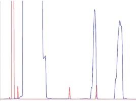
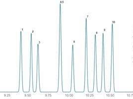
Figure 1 illustrates this point.
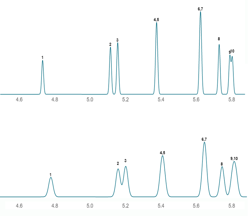
Figure 1: Detrimental effect on the resolution of organochlorine pesticide analytes when efficiency (plate count) is reduced (only a partial region of the chromatogram is shown). This is particularly noticeable in the separation of peaks 2 and 3 (PDB2 and PCB3).
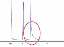
Chromatographically, efficiency is typically measured via peak width as a function of retention time as shown in Figure 2.
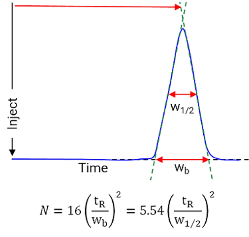
Figure 2: Measurement of chromatographic efficiency
Clearly, the broader the peak, the lower the N value for the chromatographic system.
It’s helpful to understand the relationship between efficiency and resolution and this is defined by the simplified form of the Resolution Equation;
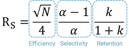
As we can see, the efficiency, as defined by the number of theoretical plates ‘N’, is directly related to resolution. As the N term in the equation is a square root function, assume that halving the number of plates will reduce the resolution between any two peaks by a factor of 1.4 (i.e. the square root of 2).
So, given the importance of efficiency to the separation of complex mixtures or when resolution is limited by the selectivity of the system, it’s worthwhile spending a little time investigating how to recognise, diagnose and fix problems with efficiency in gas chromatographic systems.
The concept of the ‘plate’ comes from fractional distillation, and the fact that the more ‘plates’ or traps that one has within a distillation column (tower) the narrower the boiling range that can be extracted from each plate (trap) – hence the analogy between the narrow boiling range of the fraction and the narrow chromatographic peak. The more plates we have within the chromatographic column, the narrower the peaks. In gas chromatography, one plate is analogous to a single adsorption and desorption event of the analyte into the stationary phase. So, for a column with 100,000 plates, the analyte will adsorb into and subsequently desorb from the stationary phase 100,000 times. Table 1 describes a typical plate count for GC columns of various dimensions;
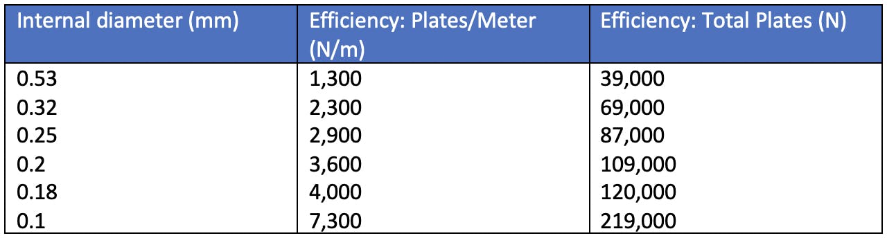
Table 1: Efficiency of GC columns of various internal diameter; 30-meter column, calculated at k’ = 6.00
Table 1 shows the internal diameter of the GC column is a factor in determining the inherent efficiency of the GC column. However, the column length is also a fundamental determining factor in the column efficiency. We can use the following relationship to help understand these effects;
N=L/H
Where the N is the plate count, L the column length and H the Height Equivalent to a Theoretical Plate (which can be assumed to be constant with constant stationary phase chemistry and carrier gas).
Therefore, doubling column length will double the efficiency (N) and improve resolution by a factor of 1.4. Halving the column length will halve the column efficiency and reduce the resolution by a factor of 1.4.
In terms of GC column stationary phase film thickness, this can affect the efficiency of earlier and later eluting peaks in different ways. Analytes with a k’ value of <5 may show reduced efficiency as film thickness is increased and vice versa for analytes with k’>5. However, unless film thickness is changed by a large amount (changing from a 0.1mm to a 1mm film thickness for example), the effects of changing film thickness should not be too drastic.
These values hold true for isothermal separations and differ for gradient temperature programmed separations, however the trends still hold true.
The information above will allow an estimate of the expected plate count, and hence efficiency, of the column we have selected for our analysis and therefore, any major deviations away from these expected values can be viewed as worthy of investigation and troubleshooting.
The final piece in the jigsaw regarding the underlying theory of efficiency in GC is the effect of the carrier gas chosen and its flow rate through the column. Figure 3 shows that the various carrier gases available give the best efficiency (lowest height equivalent to a theoretical plate (HETP, H)) at different carrier gas linear velocity. Linear velocity is a function of both column inner diameter and flow rate.
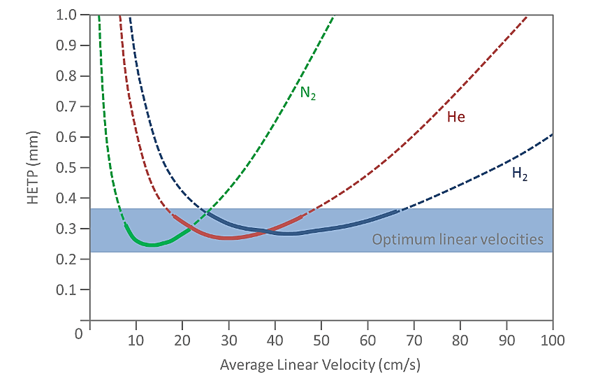
Figure 3: Plate heights achieved by various GC carrier gases over a range of carrier gas linear velocities.
This is mentioned specifically as there are some very common issue associated with the failure to achieve the best efficiency from their instrument set-up. The following points are worthy of note;
1) Check the linear velocity of the column used with the desired carrier flow rate to ensure that the combination lead to the optimum efficiency/lowest plate height (as indicated by the blue region in Figure 3). Hydrogen shows an optimum linear velocity around 50 cm/sec, Helium around 30 cm/sec and Nitrogen around 15cm/sec. The linear velocity of the carrier gas will be indicated either from data acquisition system or the instrument front panel.
2) Ensure that the column dimensions are correct within the acquisition method (including any adjustments made by trimming the column length). If the column dimensions are incorrect, the linear velocity of the carrier through the column will be incorrect and the efficiency of the separation will be compromised.
If the column dimension or carrier gas into the instrument are set incorrectly, retention times may also change alongside the reduction in chromatographic efficiency, which is a great further diagnostic clue in this respect.
Aside from these methodological considerations, what other factors can cause a reduction in efficiency of the separation? There are a vast number of answers to this question. Outlined below are some of the common problems that lead to efficiency reductions.
Column Installation Issues
It’s very important to ensure that the GC column is properly prepared (cut and cleaned) and installed in the correct way into both the GC inlet and detector. Poor column cuts will lead to a slower transfer of analyte from within the sample inlet which may result in broader peaks if thermal or solvent focussing processes are not built into the method. Typically, this problem is accompanied by some degree of peak splitting or tailing.
The correct positioning of the column within the inlet and detector are also crucial. The inlet column position will again allow for optimum transfer of the analyte into the column and is particularly important when operating the inlet in split mode. The positioning of the column in the detector will dictate the amount of unswept volume between the column outlet and the detection region within the instrument. This is particularly vital as the carrier gases is so diffuse and any void volume will be amplified in its detrimental effect on system efficiency. Ensure that you are closely following manufacturer’s instructions. For further information, see part 1 of the series on peak tailing.
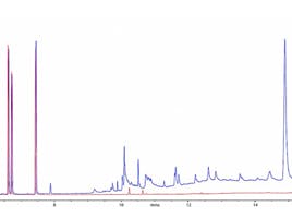
Column Contamination/Ageing
All GC columns age and have a finite lifetime. Over time, the inlet end of the column may become coated with sample matrix components and the stationary phase may be disrupted, which usually results in the ‘creep’ of stationary phase down the column, forming a thick ‘bubble-like’ region of stationary phase film which is infamous for reducing the separation efficiency. The initial region of the column encountered by the sample is critical for the quality of the chromatography. As such, ensure that the phase quality is pristine in this region. Typically, this issue is remedied by trimming a short length of column and re-installing and it may be that a meter or more of column trim is required to restore performance. Always trim the least amount required to restore good performance and if significant trims are made, don’t forget o adjust the column length within the instrument to ensure retention time reproducibility and the correct carrier gas linear velocity. It is always a good idea to have gas traps installed in the carrier gas supply lines to ensure column (phase) longevity (moisture and oxygen traps as a minimum) and that columns are conditioned in the correct manner. Again, for more information on these topics see this article on GC column conditioning.
Proper sample preparation is also important in column longevity. The cleaner the sample prior to analysis, the longer the column will last and the fewer inlet maintenance operations will be needed.
Sample Introduction Conditions
There are many factors which can influence the efficiency of a separation which are directly related to the way in which the sample is introduced into the GC system. The inlet liner cleanliness and deactivation is a primary consideration, especially in split injection as any active sites within the liner may disrupt the transfer of the analyte into the head of the GC column. This will be particularly noticeable when dealing with polar analytes. Whilst liner cleanliness is usually associated with peak tailing, if the liner is not too heavily soiled or is showing only slight signs of activity (loss of deactivation coating) then a general broadening of peaks may be the result. Ensure liners are cleaned, maintained and, if necessary, deactivated on a regular basis.
The sample injection conditions are also especially important when performing splitless injection, in order to avoid reduced peak efficiency. More information can be gleaned from 5 ways to improve your Split / Splitless Injection technique.
In summary,
- The splitless time should be long enough to transfer all analytes to the column but short enough not to have the solvent slowly bleed from the inlet causing chromatographic disruption
- The initial oven temperature should be at least 10oC below the boiling point of the sample solvent
- The stationary phase polarity should match that of the sample solvent and if this isn’t possible, an uncoated retention gap of at least 1m length should be placed between the inlet and the analytical column.
If not met, the conditions above will lead to analyte peaks which are broader than necessary, primarily due to the lack of focussing of the analyte band as it slowly enters the GC column from the inlet, hence efficiency will be reduced.
Cold Spots
It is important that the analytes that are swept through the system within the bulk of the carrier gas do so in an uninterrupted fashion. Therefore, any ‘spots’ within the carrier flow path which are cooler than their surroundings will act to disrupt or slow the passage of the analyte through the column and will effectively act as areas of dead volume within the system.
Typically, cold spots occur at the inlet if the thermal lagging between the inlet and the GC column is removed — that little cup with the lagging inside which sits below the inlet is there for a reason and shouldn’t be removed. The same is true for the insulation which sits below the detector unit and is also the reason why the any transfer lines into the MS detector are also separately heated and the transfer line temperature should be carefully checked to ensure it is set to at least the top temperature with your oven program!
Temperature Program
Many good separations are ruined with the imposition of an inappropriate temperature program. This is especially true when considering the initial oven temperature program and hold time with split injection. As noted earlier, temperature programmed separations do tend to produce more highly efficient peaks, especially for the later eluting components, however it is crucial to ensure that initial program conditions are appropriate for the sample under test and the requirements of the separation, as well the sample introduction method, either splitless or split injection. With split injections, the rule is generally that we don’t want to ‘slow’ the analyte progress through the column too much as excess sample dispersion will occur. Ideally, the initial temperature should be around 45oC below the elution temperature of the first component within the chromatogram, which can be calculated from a screening experiment (50oC to the upper gradient limit of the column at 10oC per minute is typical). As the initial hold time, unfortunately this is really a matter of trial and error, starting with a 1-minute hold and raising or lowering the initial hold period in order to assess the effects on selectivity, effciency and resolution. Again, for a more in-depth treatment of this subject see our article on insights into a more logical approach to GC temperature program development.
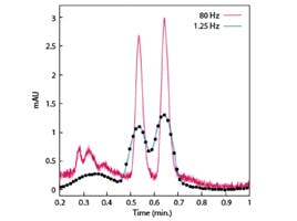
Detector Sampling Rate
The correct ‘modelling’ of the peak within any chromatographic system will be dependent upon the number of data points which are captured across the peak. With high-efficiency techniques, such as capillary GC, it is necessary to pay particular attention to the sampling frequency of the detector. This is especially true with mass spectrometric detectors, where the inherent sampling frequency tends to be lower (especially in full scanning mode). If the detector is capturing only a few data points across the peak, they may appear to be broader than they are, especially if the peak apex is missed by the detector. Follow your manufacturer’s instructions to find the optimum sampling frequency for the detector in use.
In any event, it is advisable to keep a reference chromatogram for a routinely used method when the column is new and the conditions optimised, which can be used as a reference to assess the magnitude of any decreases in efficiency over time. Judicious use of system suitability tests (SSTs) is also wise, to assess the performance of the instrument prior to an analysis and an assessment of efficiency is typical as one of the SST criteria.
Whilst efficiency is a key driver in successful separations with capillary gas chromatography, there are many other factors to consider when troubleshooting low efficiency problems. Most issues arise from the instrument set-up and the ageing of the GC column. Troubleshooting the set-points in the method followed by column and inlet maintenance is a sensible order in which to carry out your investigations.
Related articles