09 Jan 2018
Troubleshooting GC peak shapes
By Tony Taylor
Sometimes troubleshooting a separation can rely upon the end user spotting subtle clues within the chromatogram and at other times the visual signs can be much more obvious.
I like to include real world examples in my teaching, as they more effectively portray the appearance of peaks and baselines which are not as they should be. This helps students to fine tune their ‘trouble radar’ and to spot issues as they occur – accelerating the experiential learning that may otherwise take months and years to accumulate.
I want to share some of the most common issues that we see with peak shapes in Gas Chromatography in the hope that if you spot some of these in your own work, you may be able to intercept problems and deal with them more effectively.
Example 1 – Peak Tailing
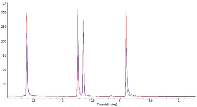
Figure 1: Chromatograms showing worsening peak tailing effects.
This example shows two overlayed chromatograms in which the peak tailing is becoming more pronounced (blue chromatogram has peaks which tail more than the red chromatogram), however both are suffering from the problem. Sometimes the phenomenon of peak tailing can be more subtle and may require you to zoom in, in order to see the issue. Tailing is measured using Tailing Factor (Tf) or Asymmetry Factor (As) and an asymmetry or tailing factor above 1.5 would indicate that tailing is sufficient for you to investigate the problem.
Tailing can cause a reduction in resolution between peaks and can make integration (and hence quantitation) less accurate and reproducible – so it’s something that we want to avoid.
Issues with peak tailing can be caused by many factors including (in priority order that I would investigate the problem)
- Poor column cut at the inlet – column has a ragged cut or is not cut at 90o to the column wall. Re-cut the column (2-5cm) and inspect the quality of the cut with a magnifier or low power microscope
- Column is improperly placed within the inlet – the end of the column is not at the correct height within the inlet. Check column placement (following manufacturer’s instructions)
- Polar or ionogenic analytes are interacting with ‘active’ sites within the liner or the head of the column. Use a fresh (deactivated) liner or trim 10-20cm from the front of the column. Note that retention time windows may need to be slightly adjusted to account for small changes in peak retention times
Whilst these are the main causes of peak tailing – there may be other issues, however checking and correcting the issues outlined here should take care of most of the problems. For more subtle problems, you can use the ‘Ask the Expert’ function within CHROMacademy to seek help on your own individual problem.
Tailing doesn’t always have to be so subtle and I’ve shown below an extreme example where solvent peaks (present in the sample at trace levels) show very bad peak tailing.
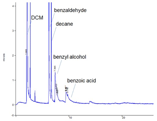
Figure 2: Pronounced peak tailing in a residual solvents GC method.
This example highlights a good tip when troubleshooting tailing peaks. If ALL of the peaks within the chromatogram tail – then the issue is more likely to be physical (poor column cut / poorly positioned column) than chemical (secondary retention of polar analytes)
Example 2 – Peak Fronting
Can also be a very subtle phenomenon but again can affect the resolution, especially in very convoluted chromatograms, or the reproducibility / accuracy of peak integration.
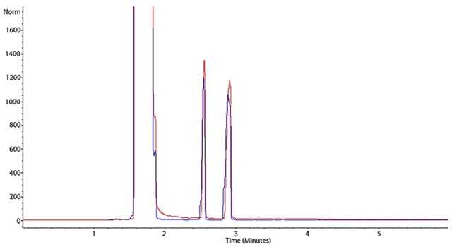
Figure 3: Subtle peak shape deformation that is known as Peak Fronting.
In Figure 3 we again see two chromatograms which show a worsening degree of peak fronting (blue more pronounced than red).
In many cases the cause of peak fronting is an overload of the GC column produced by the injection of too great a mass of analyte. One must realise that a GC column contains a very small amount of stationary phase, a 30M column may only contain a few milligrams of stationary phase material depending upon film thickness, and so the phase can be quickly occluded by adsorbed analyte which causes the excess analyte to flood forward in the column. This produces a concentration gradient which manifests as a peak ‘front’ at the detector end of the column.
Almost always the trick is to reduce the amount of analyte introduced into the column and the check that I would implement in this case are (again in priority order – which is influenced by the ease with which potential causes may be checked and eliminated as well as likelihood);
- Check that the split setting is correct and that the split flow is at the correct flow (here I mean that you need to check the instrument split outlet with a gas flow meter!). Confirm or correct as necessary
- Check that the correct injection volume has been set within the method and that the correct syringe volume is being used. Most autosamplers rely on a stepper motor to control injection volume so a setting of 0.1μL using a 1μL syringe will produce a 1μL injection if a 10μL syringe has accidentally been installed on the autosampler!
- Check the film thickness of the GC column used. Thicker stationary phase films can cope with higher analyte loadings and a 1μm film can withstand a much higher loading than a 0.1μm film.
- Check the concentration of your sample. Usually a painstaking review of your sample preparation procedure against what has actually been done during sample prep. Check reagent strengths, glassware volumes and volume settings on positive displacement pipettes!
Again – this is not an exhaustive list, but one which should cover a lot of the causes of analyte overload that are seen in the laboratory.
If you suspect that overload to be your issue, look at the detector response counts and peak apex retention times or overlay your chromatogram with one you know to be less troublesome. Sometimes a ‘big picture’ can reveal a big problem as I’ve shown in Figure 4.
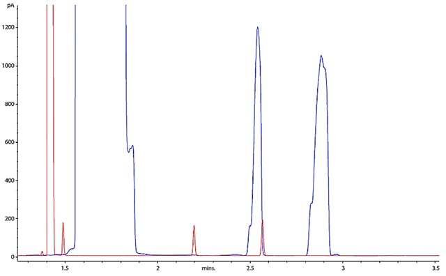
Figure 4: Overlaying current and previous chromatograms can often help us to see the big picture – and spot the obvious overload that is occurring with the blue chromatogram.
Example 3 – Peak Splitting
Is typically exemplified be a peak which has two apices or a ‘ragged’ peak apex and this effect can be very subtle as seen in Figure 5. However the ramifications on reproducibility of peak integration (and therefore peak area) can be great and indicates that the system is operating sub-optimally.
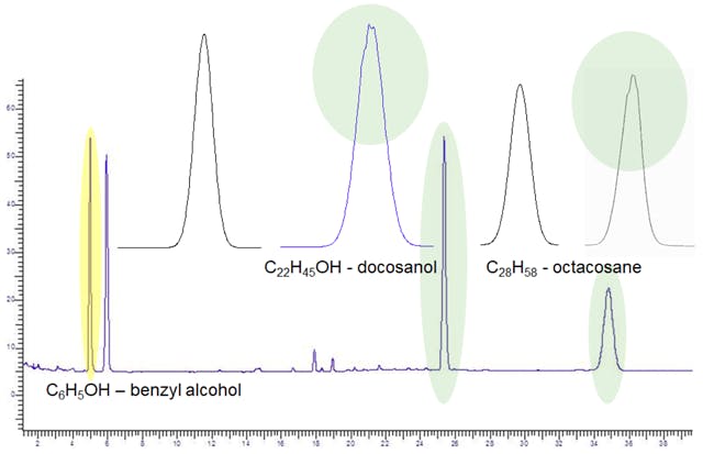
Figure 5: Subtle peak shape deformations at the peak apex and shoulder which can be described as Peak Splitting.
To give you some ‘hope’ in spotting these issues, I’ve shown in Figure 6 just how bad the problem can become when the peak splitting becomes a real issue and this trace analysis highlights the problem nicely.
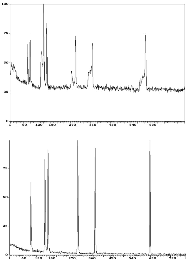
Figure 6: More pronounced peak splitting during this trace splitless analysis (top: bad chromatogram, bottom: good chromatogram). Note retention times are in seconds (s).
Peak splitting can be caused by both chemical and physical effects, a little like the peak tailing that we saw in Example 1. Special care needs to be taken when operating in splitless injection mode as, despite the name we give to the injection technique, peak splitting is more likely, as I will explain below.
So, likely causes and remedies in priority order are;
- Improperly cut column or occluded stationary phase at the head of the GC column
- Occluded stationary phase (i.e. phase has adsorbed involatile matrix material)
- Improperly positioned column in the GC inlet. As with the problem involving peak tailing, remake and check the column cut, ensure the column is correctly positioned in the inlet and if necessary, trim 10-20cm from the front of column. ‘Physical’ causes such as these described in points 1-3 are indicated when ALL of the peaks within the chromatogram are splitting. Where only certain analytes show the splitting behaviour, then chemical effects are much more likely
- Issues with sample diluent and or initial oven temperature during splitless injection. In splitless injection, the analyte is more slowly evolved from the inlet into the GC column, which would naturally produce very broad peaks. To overcome this issue, we employ a lower initial oven temperature to ‘focus’ the analytes using two phenomena – thermal focussing (the analytes condense on the stationary phase at a point in the temperature gradient between the hot inlet and the much cooler GC column within the oven) and solvent focussing (more volatile analytes contained within the sample solvent condense in a film on the GC stationary phase, this film then evaporates to produce a narrow analyte band).
For these processes to occur correctly, several factors need to be considered as outlined below:
i) The initial oven temperature should be 20oC lower than the boiling point of the sample solvent. If the initial oven temperature is too high then broad and/or split peaks will occur as the higher mid to higher boiling analytes analyte will not efficiently condense in a narrow band on the stationary phase.ii) The stationary phase chemistry should match the polarity of the analytes and especially the polarity of the sample solvent. So, trying to carry out splitless injection on a Wax column with hexane as the sample solvent will produce spit peaks.
I hope that the above information can help you to recognise problems in your gas chromatography, and perhaps more importantly to quickly fix the underlying causes.
Other troubleshooting topics in Gas Chromatography, an online GC troubleshooter, and a selection of troubleshooting webinars can all be found at www.CHROMacademy.com.

Tony Taylor, Chief Scientific Officer, Element Life Sciences (EMEAA)
Tony has worked as a chromatographer in the Pharmaceutical, Polymer, Contract Analysis and Consulting Industries for more than 35 years. His experience includes; HPLC and GC method development, development and troubleshooting of LC-MS and GC-MS methods, HPLC stationary phase characterisation, targeted and untargeted trace analysis, GC-MS spectral interpretation, solid phase extraction and development of sample preparation methods. Tony is a founder of CHROMacademy and has delivered training in chromatographic analysis to thousands of students globally.
Related articles