02 Nov 2017
HPLC Filtration - Rocks, Boulders and Sand
I get asked a lot about the value of mobile phase filtration and, especially since the introduction of UHPLC, the various system filters and how best to protect HPLC systems to allow maximum ‘up-time’. I’ve collected together here an assembly of thoughts on all things filtration for HPLC – and how to deal with various nasty’s – from Rocks to Sand.
First – what’s the point of filtration? Mainly to protect the HPLC system and analytical column from damage due to the build-up of particulate materials. Particulate build up usually results in an increase in system back pressure, to the point where the maximum system operating pressure is exceeded and the system shuts down. If the particulates are collecting at the head of the analytical column, then peak shape deformations, such as peak shouldering or tailing, can occur (more on this later). Particulates also act to damage the pump piston and piston seals, resulting in undulating baselines, fluctuating back pressures and ultimately a leak from the pump head. They can also score the rotor-seal within the autosampler (or manual injector), causing irreproducible injection volumes, poor quantitative reproducibility and, again, ultimately a leak from the injector.
Of course – the issue with particulate materials is that they come in a range of sizes, and one needs to protect from the boulders using reasonably ‘coarse’ filter materials, down to some very small particles indeed (sand), which may need a very small pore size filter to remove them. Filter porosity is also a distribution, with some such larger and much smaller pores than the nominal porosity may indicate.
So – how do we stop all of this from happening? How paranoid do we need to be?
Let’s take a look at all of the possible filtration stages which may be included within in your HPLC experiment.
- Filtration of the mobile phase through a membrane filter during preparation
- Filtration of the sample using a membrane filter during preparation
- Filtration of the mobile phase by the fritted material of the ‘sinkers’ used in the eluent reservoir
- Built-in filter in the pump check valves (selected manufactures only)
- Filter on the pump outlet path (selected manufactures only)
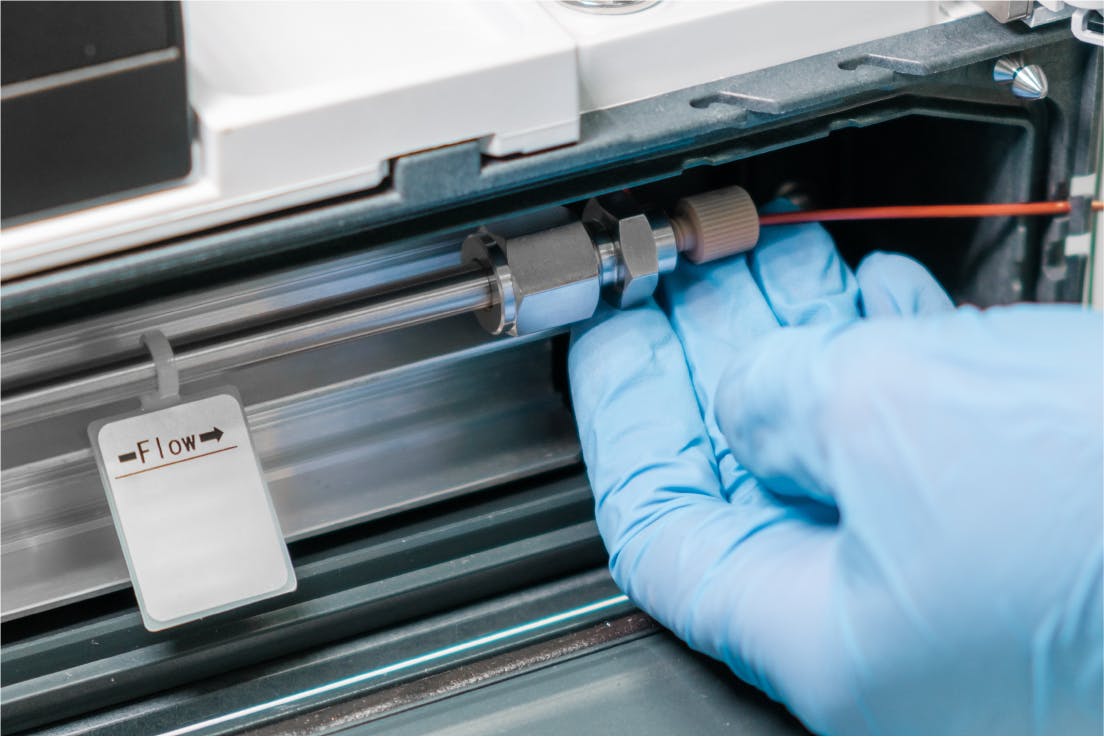
- In-line filter between the autosampler and the HPLC column (typically user fitted)
- The frits which hold the packing material into the HPLC column
So, there are several opportunities to protect our system from the possibility of blockages or component damage.
Let’s take each one in turn to decide upon the most sensible approach to the filtration we provide, based upon our system, time constraints, and budget
Particulate material is usually introduced via the glassware we use to prepare our eluent and samples and from any additives which we may use (solid or liquid buffers, pH adjusting reagents etc.). The requirement to filter at this stage always depends upon your application, equipment, and throughput. A lab with lower throughput, using standard pressure systems with 5 µm column packing materials may decide not to filter their mobile phases and have no issues with column or system longevity (I’m assuming here that the laboratory personnel can define ‘a problem’ correctly – but that’s for another time!). A high throughput laboratory, using UHPLC equipment may see a real benefit from membrane filtration during eluent preparation.
Here we need to consider the actual pore / frit size which is recommended for the various stationary phase particle size / system combinations.
<3 µm particle size packing material – use a 0.2 µm porosity filter
>3 µm particle size packing material – use a 0.45 µm porosity filter
The above recommendations can be justified using the particle size distributions that are given by a range of manufacturers for a variety of columns. The frit porosity will reflect the porosity of the inlet and outlet frits used for specific column particle size distributions.
PTFE and PVDF filter materials will have the widest chemical compatibility and are most effective as physical filters. Check the chemical compatibility with your matrix / solvent and also, importantly, with your analyte in terms of adsorption, if sample filters are used. Any investigation of quantitative irreproducibility should include the possibility of analyte adsorption onto membrane filters used in sample preparation.
When using smaller pore size membranes – eluent filtration / degassing rates should be reduced to prevent cavitation leading to the introduction of excessive amounts of air or the loss of volatile components from pre-mixed mobile phases.
Eluent reservoir sinkers are usually very coarse in terms of porosity – typically around 10 µm and are there only to catch any ‘rocks’ which may be present within our eluent system. Typically these will be constructed from sintered quartz or stainless steel and can be cleaned using a soak in 0.1N nitric acid, followed by copious rinsing with methanol. Sonication of the sintered quartz sinkers should be avoided due to the possibility of creation of small quartz particles which become part of the problem rather than the solution!
One should be aware of the type and porosity of any filters present in the pump system and follow manufacturer’s guidelines on changing these. You should also be able to spot the symptoms that indicate that the filters need changing. These will typically include undulating baselines (blocked check value filters) and low or excessively high back pressure. Modern UHPLC systems tend to have 0.2 µm porosity filters built into the pump at some point.
Many end users choose to include an in-line filter between the autosampler and the analytical column and this is especially relevant when eluent filtration is not employed, when samples are dirty (or known to contain particulate materials), when solid buffers are used, or when using UHPLC systems. The recommendations given above in terms of filter porosity should be followed for in-line filters. The actual filter used in these devices is typically disposable and the requirement for filter change is typically initiated by a sharp rise in system back pressure. In UHPLC systems, one should be careful to choose a design which is capable of operating at increased back pressure and which adds the minimum possible extra column dead volume to the system to avoid unnecessary peak broadening / loss of efficiency. In-line filters which connect directly to the end fitting of the analytical column are very popular.
Column manufacturers will typically also follow the general porosity vs. particle size recommendations given above. Implementing all of the above recommendations should very effectively prevent the blockage of column frits; however, symptoms of blocked column frits include slowly increasing system back pressure and peak shape deformation (shouldering / tailing which becomes increasingly pronounced with higher numbers of injections).
One can usually reverse the column and flush the inlet frit at slightly higher back pressure to free it of debris. Check with your column manufacturer before doing this to ensure the inlet and outlet frit porosity matches. Do not connect the column to the detector system when flushing.
Whatever strategies for filtration you employ – the key is to balance system and column longevity with cost and effort. Know what symptoms indicate a blocked filter and act quickly once they appear to avoid problems.
Related articles