08 Mar 2018
HPLC Method Transfer Problems
The overriding majority of articles on problems with the Technical Transfer of HPLC methods ultimately focus on differences between HPLC dwell volumes.
A simple Google search will bring up several examples, and if that’s a subject that you suspect may be giving you issues, I’ve also written a previous blog on this topic:
http://www.chromatographyonline.com/lcgc-blog-dwell-volume-still-relevant-our-uhplc-world
I acknowledge that this issue needs to be considered, especially given the number of different HPLC and UHPLC systems and the high pressure or low pressure mixing variants of each and the likelihood of needing to transfer methods between them. Indeed, this issue has also been widely recognised by instrument vendors, some of whom now offer the ability to adjust the ‘apparent dwell volume’ of the system within the software / firmware in order to match that of the originator lab instrumentation.
However, as the title suggests, there are many more issues which can cause problems in the transfer of HPLC methods, and I wanted to highlight some common issues that come across my desk, in the hope that it will help you avoid these problems in your own practice.
What follows is general guidance, and whilst I haven’t illustrated each item with a specific example, I’ve referenced further resources where applicable.
Check the grade and make of solvents used. There are, for example, many different grades of acetonitrile and methanol, stabilised or unstabilised THF, and matching the solvent quality used for eluent preparation and sample diluent between originator and receiving lab is very important. Try to include the manufacturer name and part number in transfer protocols where necessary.
Ensure that the sample preparation section of the protocol is fully explicit. Dissolving a solid in 50:50 acetonitrile:water or dissolving the solid in acetonitrile followed by the addition of the same volume of water may produce very different dissolution results with samples of varying solubility.
Be very explicit with the nature of the eluent preparation. As I’ ve pointed out previously, 0.1% v/v and 0.1% w/v solutions of TFA produce markedly different solution pH’s. Where the eluent pH is a critical variable, be sure to say so and indicate that care must be taken to achieve the desired value and, where possible, an acceptable range. Where it critical to prepare eluents gravimetrically, then make this explicit.
I’ve seen a rise in the popularity of buffering sample diluent solutions in order to improve the robustness of methods where analyte pKa values fall at the lower or upper end of the pH range and where ‘generic’ eluents such as 0.1% TFA, 0.1% Formic acid or Ammonia are used to achieve the desired eluent pH. This isn’t really solving the problem of the lack of buffering as the sample diluent mixes with the eluent, but it can help. However it is more unusual, and the originating lab should make an effort to explain any unusual aspects of their methods in the transfer protocol or supporting documents.
So many method transfer problems are associated with sample vials. Ensure that you include the part numbers for the vial, caps and inserts that are used for the method. Vials of lower quality may contain residues which could interfere with chromatography, may have adsorptive sites which retain certain analytes and different septa materials may contain different extractable compounds, again which can interfere with chromatography. The vial closure – whether snap cap, screw cap or crimp cap can make a difference in terms of the loss of volatile components and also the ingress of air into the vial headspace once the septum has been pierced for the first time.
I’ve known instances where results between sites have varied due to the fill level of the vials, typically due to the amount of air (oxygen) available for analyte oxidation, change of solution pH through ingress of CO2 from the vial headspace or loss of a volatile into the vial headspace. So state the typical vial fill volume if you know this to be an issue.
If you filter the mobile phase or the sample solution, you need to be very explicit about the filter type used (including part numbers where appropriate). Different filter materials will have different absorptivity characteristics and so should not be varied. Further, the surface area of the filter may make a difference to the filtering efficiency or absorptivity, and should therefore also be matched, and this usually means using a filter of the same nominal ‘volume’. Even maintaining the same filter material and size may not be good enough as differences in the plastic housing materials between manufacturers may again mean different extractable or contaminants are released into the sample solution, again potentially interfering with chromatography.
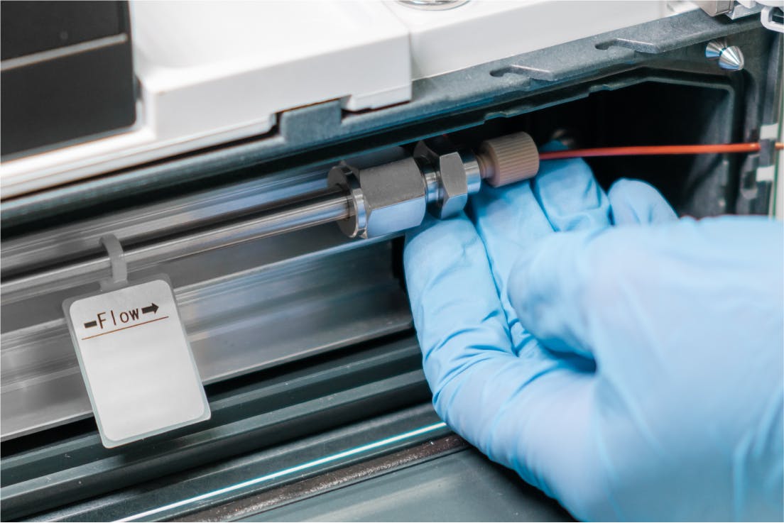
There are often measures that we take inadvertently to prevent issues from occurring and one should give careful consideration to each step of the process to consider where variability might occur. This could be something as simple as the type of cap used on the eluent reservoir. When I say cap, I mean lab film (parafilm), scrunched up blue roll, old solvent Winchester caps, the original caps supplied by the manufacturer or some retro-fit caps which include a charcoal filter to protect workers from organic solvent vapours. Any differences in the eluent reservoir cap / closure can potentially influence the ingress of CO2 or the loss of volatile components which can potentially change the eluotropic strength of the eluent and the selectivity of the separation through changes in eluent pH. Consider including a photograph of the system on which the method was validated to provide visual cues for the receiving laboratory.
Consider using constant ionic strength eluent programs. This can be a life saver in terms of baseline drift / variability and /or noise during gradient analysis and ultimately produces a much more transferable method. Note that the simplest way to achieve this it to use a quaternary pumping system, where three channels are typically used as shown in the Table below. A typical (simple) table for a ternary gradient system which produces a constant 20mM ionic strength is shown below to highlight the principle;
| Time (min) | Pump Channel A (%) | Pump Channel B (%) | Pump Channel C (%) |
| 0 | 75 | 5 | 20 |
| 20 | 15 | 65 | 20 |
A = water / B = MeOH / C = 100 mM buffer solution
Pump compressibility settings can affect the reproducibility of the gradient produced. Ensure that the method contains the correct compressibility settings (especially where isocratic or binary pumps are used) and that the receiving lab is encouraged to set these correctly as they are mostly overlooked.
There are various autosampler parameters which may vary unconsciously between laboratories and again these details should be explained as fully as possible in the transfer protocol. Depending upon the manufacturer and operating principle of the autosampler these variables may include;
- The composition of the needle wash solvent
- Whether the need wash bottle / vial is capped or uncapped
- If a flush is used to wash the outside of the needle
- The number of flushes or sample ‘pumps’ / ‘aspirations’ of the injection syringe pre and post injection
- The insertion depth of the needle into the sample vial (especially where a biphasic sample solution or supernatant above solid centrifugate is involved)
The wash program of the autosampler can be particularly important when considering the quantitative reproducibility of the method
The column re-equilibration program is typically mentioned in the method gradient timetable – however I wonder how many of us consider the impact of the system dwell volume (apologies – I promised not to mention it!) on the system equilibration time (volume)? Much is written on the ability of modern HPLC systems to reproducibly re-equilibrate, even if this is not a ‘fully equilibrated’ state. All I can state is that I’ve seen issues with resolution between critical peak pairs in a separation which was directly attributable to differences in initial eluent composition created by not adjusting a gradient table between systems with different dwell volume.
Column and eluent temperature can also be the cause of variation, especially where the fundamental heating or cooling principle differs between instruments, for example when transferring from an instrument with Peltier heating to an instrument with forced air heating. The position of the column within the column compartment may produce local differences in the temperature gradient across the column (there will always be one!). Further, the volume of the heating unit through which the eluent passes prior to entering the column for pre-warming may differ between instruments (or indeed within the same instrument!) and this should be established and matched as closely as possible. I’ve seen many issues associated with transfer between instruments in which one has an eluent pre-heating facility and the other doesn’t. Again these seemingly innocuous details have the potential to be make or break differences for difficult / susceptible separations.
There are a host of detector settings which can cause issues with method transfer, especially when transferring between diode array detectors from different manufacturers.
One needs to consider as a minimum;
- Matching the collection rate as well as any post acquisition data filtering rates
- Maintaining the spectral resolution between detectors (actually as a means of controlling the inherent signal to noise ratio between instruments). This is typically controlled by altering the slitwidth settings of the instrument (depending upon manufacturer) and some manufacturers provide a ‘resolution’ setting which controls the amount of data which is retained from the photodiode array (post acquisition filtering)
- The bandwidth setting for each discrete wavelength being acquired should be explicitly stated otherwise major differences in signal intensity may occur between the originating and receiving laboratory. Similarly, if a reference wavelength is used, both the wavelength and bandwidth of the reference signal should be explicitly stated.
- It is helpful to state the flow cell volume of the instrument used in the originator lab, as any significant variation between instruments can have a huge impact on efficiency and sensitivity.
Finally the integration algorithm used for data processing can have an impact on the success of the method transfer. Where possible the integration algorithm table (integration events table) should be included with the method, especially where the separation is complex and contains any of the following features;
- Drifting Baselines
- Split / shouldered peaks
- Poorly resolved / bunched peaks
- Badly fronting or tailing peaks
Differences between the integration processes from different manufacturers can be the cause of much frustration. Often, compliance with system suitability specification limits does not guarantee trouble free operation when ‘real’ samples are being analysed and testing rejected or retained batches is always encouraged so that the integration parameters from the receiving instrument / computer data system can be tuned to match the performance of the originator lab.
Related articles