20 Sep 2017
GC Inlet Maintenance
Many troubleshooting investigations in chromatography often don’t lead to a single causal factor. Often, the reason for problems or lack of method robustness are related to many small ‘contributory factors’ and this is particularly true of the problems associated with sample introduction in capillary Gas Chromatography.
I often find that, whilst most folks have a fair idea of what constitutes a good routine maintenance program for GC Split / Splitless inlets, the reasons for the routine are poorly understood. So, to add some deeper understanding to the problems associated with poor inlet maintenance, here is a quick multi-media blog on GC Inlet Maintenance.
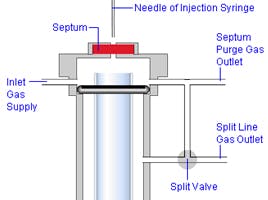
Septa: Allows the sample syringe to enter the inlet and make the injection without depressurising the inlet or interrupting the carrier gas flow.
Problems: Out gassing - Septa are made from plasticised rubber or silicon and the plasticiser materials or silicon components ‘out-gas’ giving rise to increased baseline noise or the ‘hedgehog’ baseline appearance one associates with the elution of a homologous series of analytes. This is typically overcome by a gas which flows across the underside of the septum inside the inlet to carry away these outgassing products. This is called the ‘septum purge’ or ‘septum flush’ gas flow, and has a typical flow rate of a few mL/min.
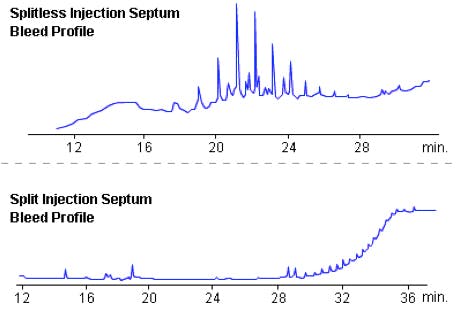
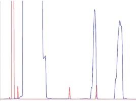
Figure 1: Typical septum bleed profiles from splitless and split injections
Septa ‘core’ or split through prolonged use, if the incorrect syringe point style is used or if the septum nut, which holds it in place, is over tightened, is badly fitting or if the septum is the incorrect size.
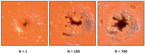
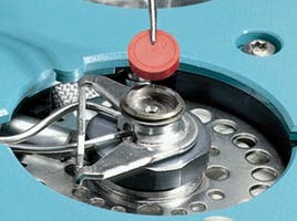
Figure 2: Coring of septa following repeated injections
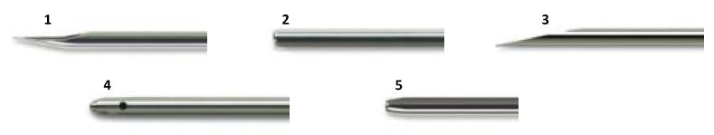
Figure 3: Needle tip styles such as type 5 cause less coring than type 3
If the septum is split or cored, then the inlet may leak during the injection phase. With very badly cored septa, the carrier will leak as the inlet pressure is increased to maintain constant flow during the thermal gradient.
Septa ‘stick’ to inlets leaving behind material on the metal surfaces of the inlet, causing inlet sealing problems and bleed.
What you see:
From shards of septum which have fallen into the inlet or from a system where the septum purge flow is too low or not working, you will see the out-gassing products of rubber and plasticiser which are usually homologous series which cause noisy, rising and ‘hedgehog’ type baselines. The same goes for septa which leave residues on the inlet metal surfaces if they have become ‘stuck’ within the inlet. If you are using an MS detector – look out for the following ions in the baseline / background which are indicative of septum bleed:
m/z 73, 207, 281, 149, 167, 279
Note that the ions at 73, 207 and 281 m/z can also arise from column bleed (polysiloxanes), however the ions at 149, 167 and 279 m/z are due to plasticisers and are particularly indicative of septum bleed. Ions at 296 and 429 indicate septum breakdown products (rather than bleed) – usually from septum shards in within the liner which are in contact with hot quartz or metal surfaces.
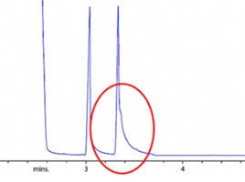
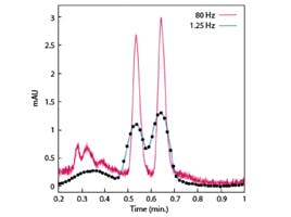
From a system which leaks during the injection phase you will see a noticeable shift in baseline position across the solvent peak and poor peak area reproducibility.
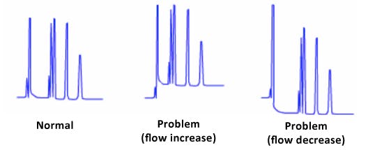
Figure 4: Shift in baseline position after injection, indicating a leak through the septum during the injection
Where the system cannot achieve the carrier pressures required at higher oven temperatures, the system may enter safety shut-down mode or you will experience a large baseline shift during the analysis with widely varying retention times.
How to stop it happening:
Ensure you have the correct septum material for the inlet temperature. Inlet temperatures above 350 oC generally require a special septum material. What temperature are your septa rated to? Why not go and check right now!
If you overfill the inlet with sample gas (sometimes called backflash), sample components will deposit onto the lower septum surface. Over time these bleed into the inlet, and onto the column, causing ‘ghost peaks’ or ‘memory effects’. What old timers like me would call ‘carry-over’. You should check that the conditions of the GC injection are compatible with the volume and solvent used for sample injection and that the volume of gas plasma formed on sample volatilisation, doesn’t exceed the inlet liner volume. See here for a nice downloadable tool to calculate sample gas volume (http://www.chem.agilent.com/en-US/Technical-Support/Instruments-Systems/Gas-Chromatography/utilities/Pages/GCCalculators.aspx)
The hole within a ‘pre-drilled’ septum acts as a centre guide and prevents coring provided that the septum is held under the correct torque.
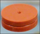 |
Figure 5: Pre-drilled septa contain a needle guide which help to prevent coring / splitting |
Choose the correct septum size for your inlet. Over-sized septa leave a ‘scone cutter’ residues around the edge of the inlet which leads to leaks and septum bleed into the inlet.
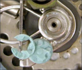 |
Figure 6: Badly fitting or lower quality septa leave residues on the inlet and ‘cookie cutter’ residues Image courtesy of Agilent Technologies, Santa Clara, CA, USA |
Some septa have ‘non-stick’ coatings which can bleed into the column and cause baseline noise and discrete low level interfering peaks. Use only high quality septa.
Install the septum according to your manufacturer’s recommendations – paying special attention to the torque of the retaining nut. Too tight and the septum will split and core much more easily. Too loose and the nut may loosen further after repeated injection, causing loss of carrier pressure and instrument shut down.
Change the septum for each major batch of analyses, for critical or trace analyses. Over a very short time you will have a positive financial payback.
Check that the actual septum purge flow from your instrument matches the method set point or instrument readout. Since the inception of highly reliable Electronic Pressure Control (EPC) systems, flow meters have become much less commonplace. However EPC systems can fail, become blocked, give rise to variable or incorrect flows just like annual valves – it really is worth checking the flow manually from time to time (perhaps as part of your PM or OQ/PV schedule).
O-rings:
Some instrument designs feature an o-ring to isolate the carrier and spilt flow from other instrument flow paths. These are typically fitted around the inlet liner or as a sealing ring around the underside of the septum cap and are made from fluorocarbon or graphite.
 |
Figure 7: |
Problems:
Depending on quality, fluorocarbon o-rings can out-gas contaminating materials at higher temperatures
- The o-ring can deform and cause leaks if not held under the correct torque.
- The o-ring can stick to the liner or inlet metal surfaces, causing sealing problems.
What you see:
Discrete peaks on the baseline – typically due to the focussing of contaminants at lower over temperatures and subsequent elution of triphenylphosphine oxide, the principal outgassing component
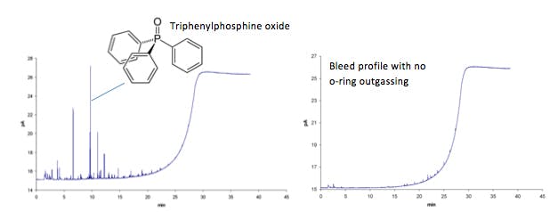
Figure 8: Outgassing products from o-rings can lead to discrete peaks within the GC bleed profile,
primarily due to the release of triphenylphosphine oxide
Look for 277 m/z in the mass spectrum of your background or any interfering peaks!
If residues of the previous o-ring remain on the liner or on the inlet metal surface, this may lead to gas flows within the inlet leaking into one another. At worst this will lead to a safety shut down, however, the problem may be more insidious and cause poor quantitative reproducibility.
How to stop it happening:
- Use high quality o-rings.
- Change the o-ring every time you change the liner (see below).
- Do not re-use liners or o-rings which have been stuck to the liner or inlet inner metal surface.
Liner, Packing and Inlet seals:
The liner is typically a tube of quartz glass which is used to constrain the gaseous sample so it does not contact the hot metal surfaces inside the inlet. In some instrument designs it acts to separate the column and split flows and is designed to be a replaceable consumable which will become contaminated with involatile sample residues over time. To facilitate sample mixing, provide a large surface area to allow volatilisation of high boiling analytes and to prevent column contamination, sometime the liner is packed with a plug of glass wool.

Figure 9: Quartz glass liner packed with deactivated quartz wool
 |
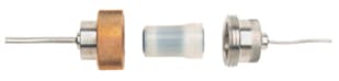
Figure 10: Metal liner seal |
Problems:
Over time, the inlet liner, packing material and seal becomes contaminated with involatile sample material, which acts as a surface to adsorb analytes through inter-molecular physico-chemical interactions such as hydrogen bonding between polar sites.
 |
 |
|
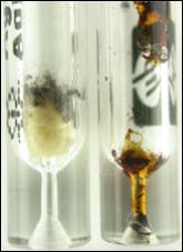
| Figure 11: Contaminated liners (left) and inlet seal (right) Image courtesy of Agilent Technologies, Santa Clara, CA, USA. |
||
Typically, the liner and packing materials will be constructed from quartz glass which contains a large number of surface polar (silanol) groups. To prevent unwanted secondary interaction with the analyte, these groups are chemically ‘derivatised’ to present a much less polar, less ‘active’ surface. Over time, the increased temperature and exposure to moisture will hydrolyse the derivatising species to the polar silanol groups and unwanted polar / polar interactions between the analytes and the liner and packing surfaces will be possible.
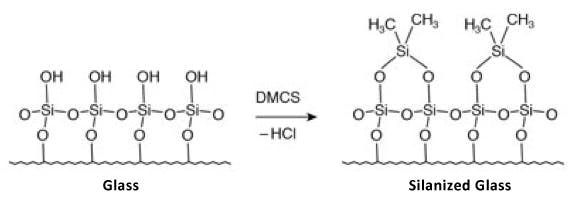
Figure 12: Typical liner / packing silylation reaction
Typically the metal seals within the inlet will also be deactivated – and the hydrolysis described above is also possible.
What you see:
Poor quantitative reproducibility and peak tailing are the most common forms of problem when inlets become active.
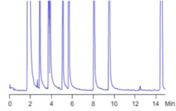
Figure 13:
Analyte peak tailing caused by unwanted secondary interactions with active sites within the liner, packing material or inlet seal
In extreme cases, analytes may not appear within the chromatogram if they are quantitatively adsorbed within the inlet.
Sometimes, analytes are not thermally stable (pesticides, carbamates, explosives, brominated flame retardants etc.) and will degrade with prolonged exposure to higher temperatures. The presence of glass wool within the liner, and especially in cases where this glass wool is active in terms of polar / polar interactions, can exacerbate the thermal degradation of labile compounds.
How to stop it happening:
- Ensure you use good quality, deactivated, liners and packing materials.
- Ensure the liner design, packing amount, density and positioning are suitable for your application.
- Ensure the liner, packing and seal are deactivated with modern deactivation process which will guarantee the highest levels of inertness.
- Change the liner as often as is necessary. This will depend on your analytes and applications, and most importantly on the nature of your sample matrix and the amount of sample clean-up that you do prior to analysis. Most manufacturers recommend that the liner is changed ‘regularly’ – and you should satisfy yourself that the liner is clean and deactivated whenever you are running large campaigns of samples, critical analyses or trace level determinations. Remember that the o-ring should be changed with each liner change and any metal seals are also changed with every or every other liner change, especially where analytes are thermally labile, peak tailing is occurring, analytes are particularly polar or trace level determinations are being undertaken.
The split line:
A large bore (typically 1/8’’) tube which carries the split gas away from the inlet. The split line may also contain a filter or trap filled with adsorbent material such as deactivated charcoal, which acts as a trap for volatile species and reduces the emissions from the instrument split line vent.
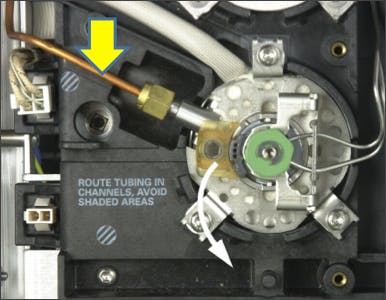 |
Figure 14: |
|
Problems:
The split line and filter (trap) become blocked over time with an accumulation of involatile material. The speed at which the tube and trap becomes blocked will be dictated by the number and cleanliness of samples.
What you see:
Contamination of the split line will result in ‘ghost peaks’ – broad baseline disturbances before or after all or certain analyte peaks. If a blank solvent is injected some or all of the peaks of the previous injection will be present, with low response and pronounced peak broadening.
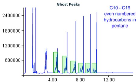
Figure 15:
Ghost peak deformations caused by, amongst other causes, re-injection of contaminants from the split line
In extreme cases, retention times may vary, this is due to the EPC unit struggling to control and balance the various applied pressures and resulting flows against the back pressure created within the inlet by the blocked split line.
How to stop it happening:
Most preventative maintenance routines should contain a check / clean / replace action for the split vent filter and the split line should be removed, inspected and rinsed or replaced as necessary. For instruments with heavy usage or when analysing large numbers of dirty samples, this action should be carried out every 6 months or more frequently if required.
Related articles