19 Nov 2019
HPLC Diagnostic Skills II - Tailing Peaks
Continuing on from HPLC Diagnostics Skills Part 1, this article goes in to further detail on peak tailing; the skills required to identify it, the causes, and (most importantly) how to fix it.
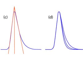
Tailing peaks are one of the most regular problems solved by our technical team. They create issues with resolution, quantitation (integration), and reproducibility. Peak shape is often the controlling factor when optimizing complex separations, especially when components are present in vastly differing concentrations. The extent at which a peak is tailing can be assessed using Equation 1.


Figure 1: TF = (a) 1.24, (b) 1.42, (c) 1.58, and (d) overlay of a, b, and c.
When methods are designed, a limit is usually set on the level of tailing that is acceptable. If you work under regulatory guidelines this may be set by the governing body. For in-house methods, a reasonable guideline is TF ≤ 2.
How do you start troubleshooting a problem when it arises?
CHROMacademy, powered by Element, is the world’s largest e-learning platform for analytical scientists. As well as Crawford’s own technical team, the popular HPLC Troubleshooter is often used to solve tailing peaks. As one of the most powerful and widely used tools on the platform, it offers a simple, fast solution to peak tailing and a vast variety of HPLC troubleshooting problems. In total, the Troubleshooter returns 25 possible causes of peak tailing—this is often not a straightforward problem to fix! So, what are the top 5 causes of peak tailing according to the HPLC Troubleshooter?
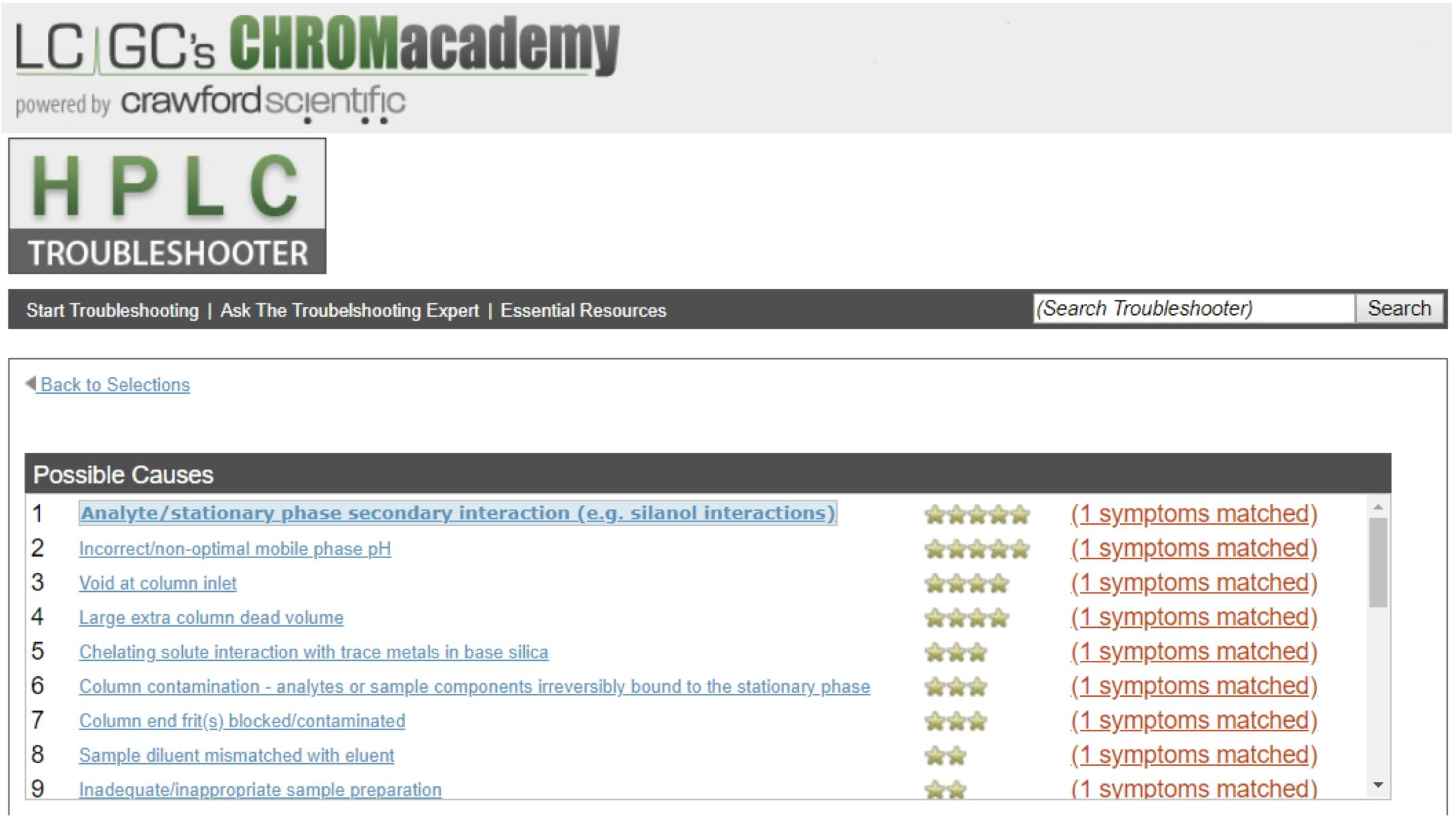
Figure 2: CHROMacademy HPLC Troubleshooter used to diagnose problems with Peak Tailing – clicking on each causal factor will give tips to identify if this is the correct cause of your problems and recommendations for fixes (https://www.chromacademy.com/hplc_troubleshooting.html)
1. Analyte/Stationary Phase Secondary Interactions
Unwanted secondary interactions between the analyte and stationary phase can lead to peak shape problems; typically, peak tailing and loss of efficiency. This may lead to a loss of resolution and difficulty with peak integration.
The most common interaction occurs between polar or ionized analyte functional groups and un-capped (un-reacted) silanol groups on a silica stationary phase surface (Figure 2).
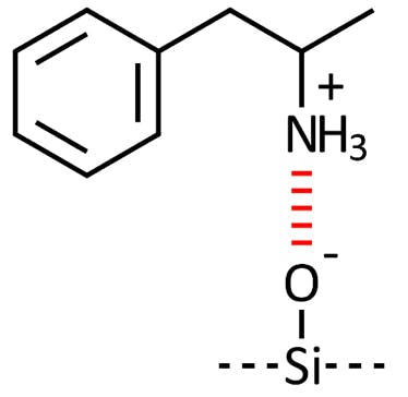
Figure 3: Interaction between a charged basic analyte and an acidic surface silanol group.
There are several ways to avoid peak tailing due to analyte/surface silanol interactions:
1. Choose a column with reduced secondary surface silanol species (end-capped, hybrid, and/or type B silica are suitable).
2. Choose a suitable pH to minimize secondary interactions: at low pH (~2.5) silanol species are non-ionized and the degree of peak tailing will reduce. At this pH, acidic species will be less ionized and, therefore, peak shape will improve. With basic species at low pH, most bases will be protonated (ionized) but the suppression of surface silanol species will mitigate the degree of peak tailing.
3. Increasing the buffer concentration (> 20 mM) or swapping the counter ion for one which is more highly surface-active may also mitigate the degree of peak tailing.
4. A more traditional method for controlling peak tailing is the use of a sacrificial base (such as triethylamine) in the mobile phase (0.05 M is typical) which is sterically small and charged at low pH. This will preferentially interact with the surface silanol species.
5. Certain analytes may chelate with metal ions on the stationary phase surface (which is either included in the silica matrix or has leached from the column internal surface or frit). This secondary interaction will also affect peak shape and produce peak tailing.
2. Incorrect/Non-Optimal Mobile Phase pH
Mobile phase pH affects retention of ionizable analytes and the selectivity of separations in reversed phase HPLC. Some methods require a very precise pH to provide robust analyses. Low pH tends to increase retention of acidic analytes and decrease retention of basic analytes, whereas, high pH tends to decrease retention of acidic species and increase retention of basic species.
Low pH (< 3) tends to improve peak tailing, especially for basic compounds, due to the decrease in ionization of acidic silanol species on the stationary phase surface.

Figure 4: Surface silanol ionization.
Buffers are used to prevent pH changes. It is important that the correct buffer system is used to prevent pH shifts (usually due to the introduction of the analyte in a diluent which does not match the mobile phase pH). pH should only be measured using a calibrated pH meter on the aqueous portion of the mobile phase. Accuracy to within ±0.05 pH units is recommended. The actual mobile phase pH may alter significantly (typically 1 to 1.5 pH units closer to neutral) in the presence of larger amounts of an organic modifier. Mobile phase pH may alter on standing through the ingress of CO2 (making the mobile phase more acidic) and via evaporation of the organic portion when pre-mixed mobile phases are used. The sensitivity of certain detection systems (such as atmospheric pressure MS and fluorescence detection) may be affected by mobile phase pH changes which affect the degree of analyte ionization.
3. A Void at Column Inlet
A void is caused by a mechanical collapse of the stationary phase material which, under system pressure, compresses the bed materials, leaving a void at the head of the analytical column.
The void often results in loss of efficiency and poor peak shape (fronting, tailing, and shouldering are typical).
Voids are typically related to silica collapse which occurs under high pressure or high pH conditions.
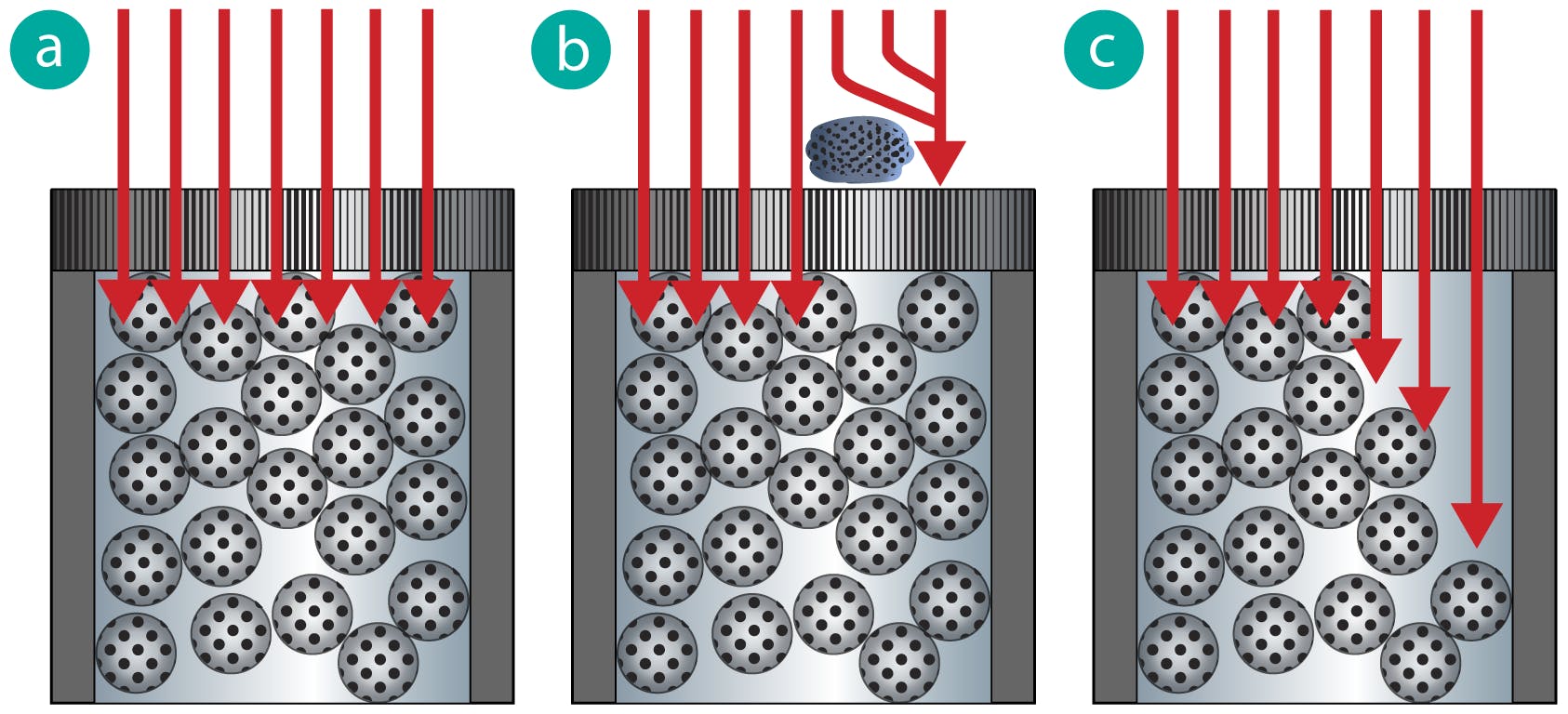
Figure 5: Schematic of the flow path through an HPLC with a) normal flow b) flow disturbance due to a blocked inlet frit c) flow disturbance due to a column void (arrows indicate flow direction prior to separation as the sample plug enters the column).
Avoid pressure shock - increase flow (pressure) gradually (some modern pumps can be programmed to achieve this automatically) and use ‘make before break’ injection valves when possible.
Operate at pH < 7.5, unless the stationary phase has been designed for use at high pH.
It may be possible to temporarily fix the problem by running the column in the reversed direction and then return to the normal flow direction. However, the void will ultimately return after extended operation.
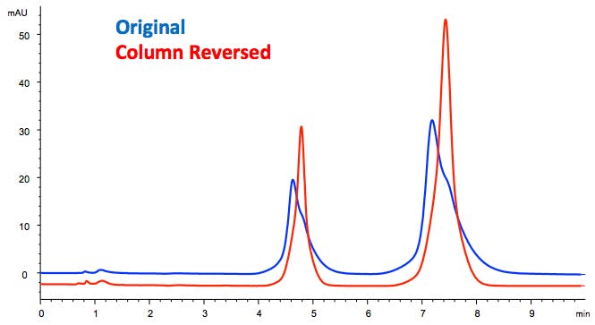
Figure 5: Peak shape recovery after column reversal to unblock an inlet frit or repair inlet void.
4. Large Extra Column Dead Volume
Extra column volume: the volume between the injection point and the detection point, excluding the part of the column containing the stationary phase. It is composed of the injector, connecting lines, frits, and the detector. This determines the extra column effects.
Extra column effects: the total band broadening effects of all parts of the chromatographic system outside of the column itself. Extra column effects must be minimized to maintain the efficiency of the column. Areas of band broadening can include the injector, injection volume, connecting tubing, end fittings, frits, detector cell volume, and internal detector tubing. The variances of all these contributions are additive.

W = bandwidth
The following are bandwidth contributions from
Wc = column
Ws = injector/autosampler
Wlc = lines and connectors
Wfc = detector flow cell
As long as the bandwidth contributions Ws, Wlc, and Wfc are each less than 0.3 W, their effect on W can be neglected.
There are many aspects of the system which add dead volume, leading to loss of efficiency and/or resolution (Figure 5 and 6). These include:
• Unnecessarily long tubing with i.d. larger than required
• Incorrect fitting type or poorly made connection
• Use of a guard column
• Use of unnecessary unions within the tubing
• Large volume accessories or components (flow cell, injection loop, etc.)
Therefore, using the correct fittings, minimizing tubing length and i.d., optimizing flow cell size for your instrument, etc. will all help to reduce extra column volume. Extra column volume is of particular importance when working with UHPLC applications.
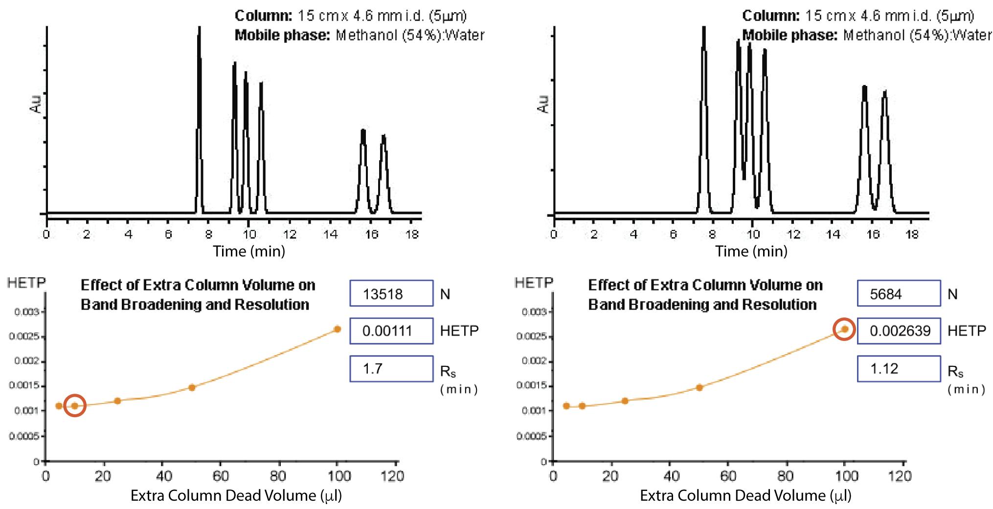
Figure 6: Effect of dead volume on HPLC resolution and separation. Left chromatogram generated with a system of 10mL extra column volume and right 100mL extra column volume

Figure 7: Effect of extra column volume on resolution and quantitation.
Measuring the extra column volume of a system is straightforward:
Step one: Remove the column and join the tubing with a zero-dead volume union
Step two: Inject 10 µL of 100% strong solvent (acetonitrile works with UV at 200 nm) or a solution of 1% acetone (monitor at 265 nm)
Step three: Interpret the extra column hold uptime. The apex retention time (tR) of the baseline perturbance due to the passage of the solvent gives this (expressed in minutes)
Step four: Multiply this time by the flow rate (in mL/min) to obtain the extra column volume (in mL)
5. Chelating Solute Interaction with Trace Metals in Base Silica
Trace metal content within or on the surface of the stationary phase material can chelate with certain analytes causing peak tailing (Figure 7). The presence of surface metals can also increase silanol activity and interactions.
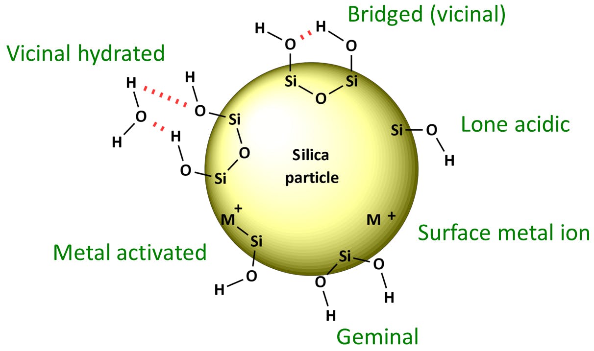
Figure 8: Surface silanol and metal moieties.
When analyzing analytes, which are capable of chelation the following will help to mitigate any peak tailing effect:
• Use high purity silica-based columns with low trace metal content
• Add EDTA or another sacrificial chelating compound to the mobile phase which will be preferentially adsorbed to active sites, reducing analyte/stationary phase secondary interactions (and mitigating peak tailing effects)
• Consider the use of polymeric phases or those known to contain low levels of metals that are likely to create tailing effects
Benchmarking
As with any troubleshooting problem, approaching it in a logical fashion and only changing one thing at a time will help you to quickly resolve the issue. Having a benchmarking method that is run on the system/column combination will highlight when they are functioning as expected. Using this method, parameters such as retention time, resolution, peak tailing, etc. should all be assessed to give you normal values. At the first sign of a problem, run the benchmarking method. If this method works well then there is a problem with the particular analysis being run. If the benchmarking method fails, then it is most likely the column or instrument which is at fault. This will allow you to quickly focus on the correct part of the analysis, instrument or method, and will greatly reduce your troubleshooting time.
Regardless, Element customers and CHROMacademy Premier members have access to a variety of troubleshooting resources. Crawford customers have direct access to our industry-leading technical team, who have all the answers (and usually at the drop of a hat). On the other hand, CHROMacademy Premier members have direct access to the troubleshooting tools (for both HPLC and GC). However, you can still contact us if you’re ever in a bind!

