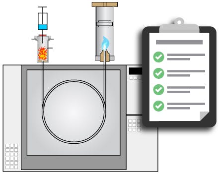
We commonly encounter troubleshooting exercises where a more in-depth knowledge and pragmatic approach to GC set-up would have been advantageous. This prompted us to produce a GC/GC-MS preparation checklist. Reference this prior to analysis to understand the actions, checks, tools, and consumable items that are required. 

Check gases are of the correct purity (99.999%+).
Turn on the cylinders.
If cylinder bottle pressure less than 30 psi replace it.
If the line pressure (second regulator stage or gauge at the bench) is below 80psi increase line pressure with a cylinder and/or bench regulator.
Verify correct gas traps are installed.  Verify that the gas filters are not exhausted and check when they were last replaced. 

Comments;

Is the GC column fit for purpose?
Has it been properly stored (out of sunlight with column ends capped)?  How did it perform last time it was used – check records?
Remove the inlet septum cap. Replace the inlet septum.

Comments;

  • Ensure you have the correct septum in terms of bleed profile and temperature resistance
  • Use pinch nose plastic tweezers to avoid scratching the metal surfaces of the inlet
  • Avoid applying excess torque pressure on the septum by following manufacturers guidelines for the inlet closure/septum nut tightening.  Failure to do this will lead to septum coring and splitting.
Open the inlet.
Inspect the inlet liner and check for cleanliness including solid debris, discolouration and dark patches of burned on matrix contaminants.
If in doubt replace the liner– check that the liner geometry/packing is appropriate for your method.
Use a fresh liner o-ring as necessary.
Replace the inlet bottom seal if necessary (follow manufacturer’s instructions).
Ensure that inlet surfaces and seals are included in medium-term maintenance / replacement schedules.

Comments;

  • Ensure that polymeric nitrile or vinyl lint-free gloves are used for all inlet maintenance operations - GC Inlet Maintenance

  • Check liner for debris, discolouration and dark contaminant residues
  • Use only plastic tweezers to remove the liner
  • A torch and dental mirror can be very useful for internal inspection of the inlet
  • Liner o-rings should be perfectly round in profile (doughnut-like) and any ‘flattening’ of the o-ring or sticking to the liner body indicates it needs to be replaced
  • Selection Guide - Capillary GC Liner Selection Guide
  • The internal body of the liner should be periodically cleaned with a suitable solvent (methanol is a popular choice) using a lint-free swab.
  • Any bottom seals should be replaced periodically to ensure that the seal does not contribute to secondary retention (peak tailing/analyte adsorption)
Replace nuts and ferrules on each end of the column.

Comments;

  • Quarter a used inlet septum and slide one quarter onto both detector and inlet ends of the column – carefully removing any septum shards retained in the head of the column.  These will be used to maintain the correct distance between the ferrule and the tip of the column on installation.
  • Various ferule materials and sizes are available and vary with column dimensions and application.
  • Graphite ferrules with the through-hole diameter matched to the column o.d. are suitable for general GC applications
  • When MS or specialist detectors are used, you may need to consider a graphite/vespel composite ferrule.
Trim the ends of the column and inspect with a magnifier or low power microscope to make sure the cut is straight and there are no rough edges.
The quality of the column cut is directly related to peak shape and quantitative reproducibility, therefore good column cutting technique is essential.

Comments;

  • Ceramic wafers and diamond-tipped wheel cutters are available for column cutting and you should take time to develop a good cutting technique
  • The amount of column trimmed each time will depend upon the amount of phase degradation at each end of the column.  5-10cm trims will usually be sufficient, however, up to 1m of column may need to be trimmed if sample matrix deposition is heavy or phase stripping has occurred.  Consider using a non-coated, deactivated guard column if excess column trimming is required
  • The requirement to inspect the quality of the column cut prior to installation will save you a lot of troubleshooting time once the column is installed
Note your manufacturers recommended column insertion distance (inlet and detector).
Wipe the outer column surface of the column ends with a solvent suitable for removing contamination from fingerprints (isopropyl alcohol is a popular choice).
Adjust the nut/ferrule position and hold in place with the ¼ septum from 6.

Comments;

  • Compliance with the manufacturers recommended insertion distance is critical to a successful analysis
  • Incorrect insertion into the inlet will lead to broad and tailing peaks and quantitative reproducibility issues
  • Incorrect insertion into the detector will lead to peak broadening and loss of efficiency (if too low in the inlet) or noisy/spiking baselines and poor sensitivity (it too high in the inlet)
Insert the column into the inlet. Tighten the ferrule and gently pull the column to check if the fitting is tight enough.  Grip the column and continue to tighten about 1/8 turn until the column can't be moved. Repeat with the detector connection.
Input column dimensions, carrier gas type, required flow rate and whether constant flow/constant pressure is to be used into the instrument.
Verify column flow at the detector using an electronic flow meter

Comments;

  • Using an electronic flow meter to verify column flow will not only check the GC operation but also that the correct column dimensions and carrier gas type have been programmed into the instrument. 
  • This is a common error when prospering for GC analysis.
Switch on the inlet and detector heaters, and the detector gas flows.
Ignite the detector if it is flame based.

Comments;

  • A dental mirror is good for checking if the detector flame has been established – hold one inch above the detector chimney and observe condensation on the mirror surface if the flame is burning
  • It is good practice to verify the flow rate of each detector gas using an electronic flow meter, although this may not be necessary prior to every analysis
Purge dissolved oxygen by allowing carrier to flow through the column at ambient temperature for 10 – 30 mins. depending upon column dimensions.
This step is important and should not be omitted.  Failure to purge the phase may lead to unnecessary column damage and increased thermal equilibration times.
Set the oven to the conditioning temperature  - 10°C above the maximum oven temperature of your method or at the gradient upper-temperature limit of the column, whichever is lower.
Allow to thermally condition for the period recommended in the guide below.

Comments;

Cool the oven to starting temperature of your analysis.
Load the test method into the GC / data system.
Check the split flow at the split outlet port using an electronic flow meter.
Check the septum purge flow using an electronic flow meter.
Perform at least 1 full temperature program according to your analytical method.

Comments;

  • It is important that the split flow is verified using an electronic flow meter as this flow path is more susceptible to partial blockage
  • When septum purge flow is automatically calculated, ensure that the flow is in the range 1 – 10 mL/min.
  • Running through the analytical temperature/flow program helps to elute phase degradants or inlet leachables/outgassing agents which have not been removed from the column during the initial thermal equilibration.  It also helps to check that inlet and detector connections are leak-free throughout the temperate / pressure program.
Perform a test injection/system suitability test to check method performance.

Comments;