19 Sep 2017
Causes of Retention Time Drift in HPLC

We have all faced the situation in which the retention time of our analytes ‘drift’ over time – sometimes to the extent which takes analytes outside their ‘retention window’ within our data processing software – causing analyte peaks to be missed. The phenomenon is often seen over long ‘campaigns’ of analysis and also when installing a new HPLC column, where several ‘priming’ injections might be required to obtain a stable analyte retention time.
But why does this happen – and what can be done about it?
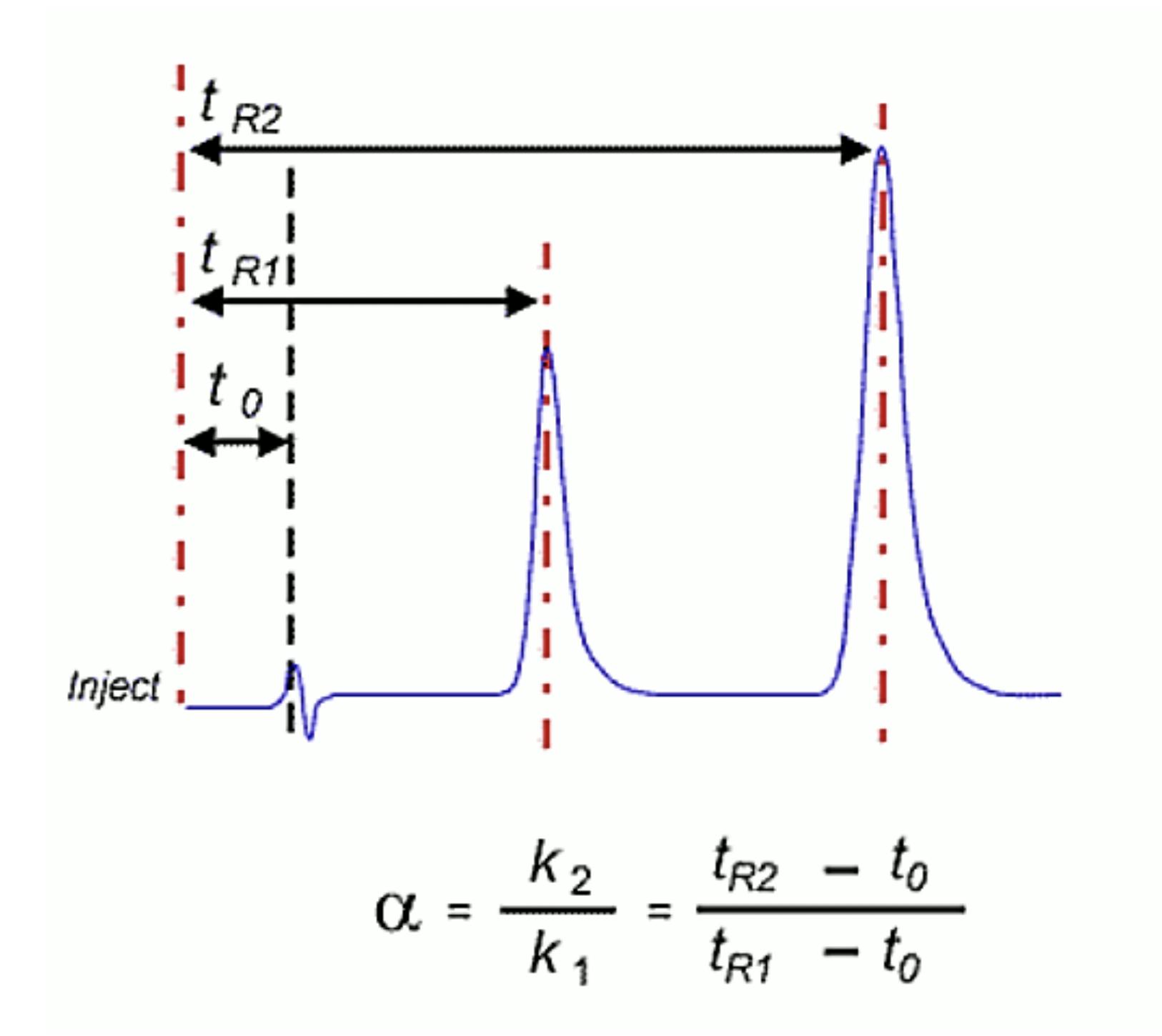
First – one should establish the cause of the drift – is it a result of changes in flow rate or a chemical change to eluent or HPLC column. This is fairly easily determined; if the retention time of the analyte peaks AND the t0 marker (or solvent injection disturbance) change to the same degree, then the problem is more likely to be related to the eluent flow rate. If the t0 marker retention time remains relatively constant and the analyte retention times change relative to it, then a chemical change in the separation system is indicated.
Before we move on to identify the causes and remedies of these problems – it’s important just to re-iterate that we are considering ‘drift’ in retention times, rather than a step change in retention behavior which may be caused by other problems entirely.
Many stationary phases contain surface species which interact with our analyte in an unintended way – these are called ‘silanol’ species and are surface hydroxyl groups which remain un-derivatised and un-endcapped during the stationary phase manufacture and deactivation (typically this would be around 40 – 60% of all the silanol species originally present on the bare silica!). They predominantly interact, typically via hydrogen bonding, with polar or ionised analyte functional groups and are a form of unwanted or secondary effect which usually manifest themselves in the form of tailing peaks.
Whilst column manufacturers take great care with the silica they use and their bonding processes, a new column may require several priming injections for the constituents of our sample to irreversibly bind to the most active of these surface silanol species – each injection being exposed to successively fewer silanol groups and hence producing a slightly different (typically shorter) retention time. Yes – we do in fact end cap our columns with our sample – which is why it’s always a good idea to start method development with a new HPLC column! Whilst secondary effects are important in this regard, we should note that the sample components which irreversibly bind to the functional ligand (C18, C8 etc.) can also be responsible for the need for priming injections – here analyte retention times can become either longer or shorter depending upon the nature of the contaminating species.
To reduce the requirement for priming injections one should choose a high quality stationary phase, which uses Type B (type II) silica and which has a low metal ion content. To speed up the column ‘equilibration’ process, consider injecting a sample at 10x the usual concentration in order to quickly cover the surface silanol species.
Finally, components of dirty or complex samples may continue to build up on the column over the course of many injections and change the nature of the interaction between our sample and the stationary phase – it’s akin to separating our analytes using the detritus within our sample, and not recommended. This is especially prevalent with gradient HPLC analysis and can be easily avoided through the use of a good quality guard column packed with the same stationary phase as your column. Note that the use of a filter will not help this situation as it is a chemical, rather than a physical, filter which is required.
Physical changes over time can also occur with our eluent systems over the course of long analytical campaigns. With pre-mixed mobile phases, the more volatile (organic) components may be lost to the headspace above the liquid surface, leading to slow and steady retention time drift of all analytes. This may accelerate with time as the headspace above the emptying reservoir becomes larger. If you suspect this may be the case, investigate the use of a pump capable of dynamic (on-line) mixing.
A similar phenomenon may also occur when using more volatile pH controlling reagents such as trifluoroacetic acid (TFA) or formic acid etc. These species may also be lost to the headspace above the eluent and cause retention time and/or selectivity to progressively change during the analysis. One should consider temperature control of the eluent reservoir, effective reservoir capping (which is why covering the top of the eluent bottle in foil wrap or lab film is a bad idea!), or moving any open reservoirs from under the air conditioning unit in the laboratory!
Changes in retention time due to flow rate changes are less common and more insidious. If the pump is suspected of producing variable flow, check using a calibrated flow meter or deliver 10mL of eluent into a measuring cylinder and record the time taken to check the accuracy of your flow rate – this is rarely the cause of retention time drift but one should not entirely rule out pump delivery problems.
The most likely cause of retention drift will be the gradual development of a small but significant leak of eluent within the system – often the leak will be so small as to not produce a physical droplet of liquid. In this instance I like to play detective with a folded piece of lab ‘blue roll’ paper which I offer up to the susceptible parts of the system, including all unions, connections, back of the pump head, autosampler injection port, column connections etc. etc., and look for the dreaded dark blue shadow as the paper draws the residual liquid from around the connection. In this case the issue can be repaired according to your manufacturers instructions. If the small leak is left unattended long enough they typically get bigger and so will be more easily located. That is unless you are using solid buffer salts within your eluent – in which case the buffer can crystallize and ‘plug’ the leak whilst the system is shut down. The buffer plug will gradually dissolve during subsequent use and the leak, and drifting retention times, will return. Look out for white crystalline deposits around the pump head, connectors and the autosampler injection port and valve.
Drifting retention times, whatever the cause, greatly impact the robustness of our analyses and should be identified and eliminated at the earliest opportunity.
Related articles