04 Mar 2020
GC Diagnostic Skills I | Peak Tailing
By Tony Taylor
Peak tailing is a problem which is regularly encountered in capillary gas chromatography (GC). It can cause issues with resolution and peak integration, affecting both qualitative and quantitative analysis. In this first of a series on GC diagnostic and troubleshooting, discover how best to identify the source of the issue, and find suggestions on how to prevent or fix the underlying problems.
The first stage in diagnosing peak tailing is to assess the nature of the tailing peaks. Ascertain if;
1) All peaks tail including the solvent peak
2) Only some of the analyte peaks tail
3) Only the solvent peak (and sometimes very early eluting analytes) show tailing
4) Only later eluting analyte peaks tail
This list has been arranged in order of frequency.
In each of these cases, it is likely that the severity of the peak tailing will range from almost non-discernible tailing (visible only when zoomed in on the base of the peak using the chromatographic data system (CDS)) to severe tailing, which can be so bad that the analyte is barely distinguishable from the baseline. The severity of the tailing will uncover further clues regarding the nature of the problem.
How might the issues be identified and remediated?
All peaks tail including the solvent peak
The situation in which all peaks within the chromatogram show tailing is probably both the most common and the easiest to diagnose. Figure 1 shows a separation in which all of the analytes within the chromatogram show peak tailing to a greater or lesser degree.

Figure 1: Capillary GC chromatogram in which all analytes and the injection solvent peak show tailing to a greater or lesser degree
Sometimes peak tailing can be caused by chemical interactions between certain analytes (usually more polar) and surfaces within the GC system. However, when all peaks within the chromatogram show tailing behaviour it’s most often due to a physical effect, that is, if the GC was set up incorrectly! Tailing peaks are usually created through turbulence within the hydraulic path of the carrier gas as it passes through the system. They may also be caused by unswept volumes within the system. Identify what went wrong with the following checklist.
Poor GC column cut
The quality of the column cuts at both the inlet and detector side is extremely important and even small imperfections can cause significant peak tailing issues. Ensure that the column cut is smooth (no jagged edges), that no debris created during the cut is obstructing the column inlet/outlet and that the cut is at right angles to the column wall. Proficiency at cutting columns and finding a preferred tool to do so (i.e. ceramic wafer, diamond-tipped pen, rotating blade cutter, etc) can prove beneficial. The quality of the cut can be inspected with a magnifying tool. A jagged cut with burrs, shards of silica, or debris can cause turbulent eddies which entrap a portion of the analyte molecules as they move in or out of the column, leading to peak tailing. Figure 2 shows the ‘chair-shaped’ peak which is highly indicative of a poorly cut column, where the column entrance is partially blocked.

Figure 2: Chair-shaped GC peaks which are indicative of problems with column inlet cut or partial blockage of the column, some examples of which are shown in the inset.
GC Column Positioning
The position of the GC column within the inlet (i.e. it’s position within the liner, inside the GC inlet) is often critical to the peak shape. If the column is too high or too low within the inlet, then the flow path for the analytes to enter the column may become convoluted, or a dead volume (unswept volume) may be created. Again, this causes a certain portion of the analyte molecules to be retained longer than others whilst they make their way in or out of the GC column, hence causing peak tailing. Whilst the dead volume phenomenon is more often associated with peak broadening, it is also possible that this may cause peak tailing. This also holds true for the positioning of the column in the GC detector and ionising (including MS) and non-ionising detectors are susceptible. One should always carefully follow instructions from instrument manufacturers for column positioning in the inlet and detector. This is typically specified as the distance past the tip of the column ferrule, insertion distance into the inlet, or the distance which the column is drawn back from the end stop (inlet liner constriction or, for example, the FID jet orifice).

Figure 3: The column length between the ferrule and the tip of the column needs to be carefully measured for the column to be in the correct position within the GC and inlet and detector
Use correct GC Column nuts and ferrules
The issues with the creation of unswept volumes are also created if incorrect column ferrules are used for installation. Always use the correct ferrule, noting that the size and material of construction are both important in this respect. Column nuts should not be overtightened during column installation. All of these factors can also be responsible for poorly swept volumes and, again, it’s important to carefully follow the manufacturer’s instructions.
If there is an issue with the way in which the column has been prepared or installed in the inlet, then it is necessary to re-prepare the column; re-trim inlet and detector ends of the column, fit correct ferrules and ensure the correct column insertion distances into both the GC inlet and detector.
Severe column contamination
If the column suffers from severe contamination of the stationary phase film (especially at the inlet end), then all peaks may also show tailing behaviour, due to the non-ideal partitioning of the analyte and/or analyte partial exclusion from the stationary phase. A high proportion of the analyte component molecules are unable to partition correctly into the stationary phase. Instead, they are adsorbed onto, or partition into, the contaminant material on the stationary phase surface. This special case of peak tailing is usually accompanied by a loss of peak efficiency (peak broadening).
If gross stationary phase contamination is suspected, and all other possible causes mentioned above have been explored, trim at least 20cm from the inlet end of the column, re-fit and assess peak shape with a sample or test mix. It may be necessary to further trim the column if not all contamination has been removed. Assess the likelihood of restoring column performance from the resulting chromatogram of the initial column trim. If necessary, more than 20cm of a column may be trimmed in order to achieve the desired column performance.

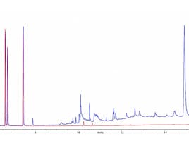
Figure 4: Mid-polarity GC column (60m) heavily contaminated with high polarity contaminant showing classical peak tailing and broadening for a test mix of analytes with varying polarity (left); same column after removal of 1.5m from the column inlet, restoring performance (right) (Reproduced courtesy of Agilent Technologies, Santa Clara, CA)
Note that column trimming is a last resort and will certainly result in small losses in column efficiency and possible retention time shifts, however, it is often enough to restore chromatographic performance for long enough to await the delivery of a replacement column.
Only some of the analyte peaks tail
Chromatograms in which only some of the analyte peaks are tailing is often indicative of a chemical interaction between the tailing analyte compounds and some part of the gas chromatographic system.
Figure 5 shows a typical example of this behaviour.

Figure 5: Specific analytes within a GC chromatogram show tailing behaviour whilst other peaks show no tailing effects
Acidic, basic, or highly polar compounds are susceptible to secondary interactions with various components within the system, including the liner, the end surfaces of the column, and any region within the column from which the stationary phase has been stripped. Some proportion of the molecules of each more polar analyte will undergo secondary interactions, usually with exposed silanol groups, causing unwanted retention which is greater than the bulk of the analyte molecules. Hence, peak tailing.
Silanol groups are the polar hydroxyl groups found on the surface of silica-based substances. They are typically present in the locations mentioned above as well as on the surface of inlet packing materials (glass and quartz packings). These silanol groups, depending upon their configuration and the nature of the underlying silica, are highly polar and sometimes acidic, and will tend to form strong hydrogen bonds with polar, acidic, and basic analytes, leading to peak tailing.
There are several actions which can be taken to avoid or remediate these issues including;
- Using chemically (manufacturer) deactivated liners, GC columns and fittings. The chemical deactivation effectively ‘caps’ the polar silanol groups within each component as shown in Figure 6

Figure 6: Schematic of a chemical deactivation reaction - note various reagents can be used for deactivation
- Carefully, choosing the materials of construction for the GC inlet liner to be as inert as possible; especially, when dealing with polar compounds which are susceptible to secondary retention effects. An example here might include the choice of a highly inert liner packing material such as Tenax or Deactivated Carbon
- Ensure that the GC column is regularly trimmed to remove and exposed silica surface which has been stripped of stationary phase and ensures that GC columns are of the highest quality, inspecting for burrs, roughness, or residual silica material on every occasion
- Regularly change the inlet liner, as over time the deactivating agent will re-hydrolyse (especially when injecting aqueous or aqueous containing solvents), re-exposing silanol groups on the liner surface and packing materials.
Adopting regular column trimming and inlet liner maintenance into preventative maintenance schedule will help enormously to reduce the instances of peak tailing through secondary retention effects.
There is one further phenomenon which deserves a mention when troubleshooting individual analyte peak tailing—thermal decomposition. When a thermally labile analyte decomposes in the high-temperature environment of the GC inlet, the decomposition products may retain a chemically similar nature to the analyte and therefore elute relatively close to the analyte peak, which can sometimes resemble peak tailing. Of course, this phenomenon may occur with only certain peaks within the sample mixture and this may appear, initially, to be caused by secondary chemical interactions or adsorption.
If thermal decomposition is suspected, there are two investigative tools which can be used;
a) Lower the inlet temperature by 50oC and re-assess the peak shape as well as the quantitative performance of the analysis as a whole (the volatilisation of other analytes may be affected by this reduction in inlet temperature)
b) If using splitless injection, apply a small split (5:1 or 10:1) in order to reduce the residence time of the analyte within the inlet. Again, re-assess the peak tailing and analytical performance of all components of interest as the introduction of a split may reduce the sensitivity of the method
Only the solvent peak (and very early eluting peaks) shows tailing
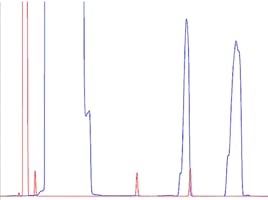
This special case of peak tailing is worthy of note as it occurs frequently. Figure 7 shows the case in point where the blue chromatogram shows the problematic behaviour involving the solvent and very early eluting analyte peaks.

Figure 7: Tailing of the GC solvent peak and early eluting analyte (blue) and the resulting chromatogram (red) after optimisation of the splitless time
This problem is almost always related to the effective overloading of a system by the sample injection solvent and occurs, almost exclusively, when employing splitless injection techniques. In this injection mode, the sample residence time within the inlet liner is much higher relative to the split injection mode and, unless the inlet is ‘purged’ of the sample solvent, it will slowly bleed from the inlet, decaying over time. This creates the illusion of a badly tailing peak.
A full treatment of the underlying principles is beyond the scope of this article. Nevertheless, an effective way of quickly emptying the liner post sample transfer to the GC column must be found.
This is achieved by activating the split valve to empty the inlet, at some set time after injection, when its certain that all analyte components have been transferred to the GC column. This is the splitless time or purge time. The time at which the split valve is opened can be practically assessed by measuring the peak area of a selected early eluting analyte at different splitless times and selecting the shortest splitless time after which a constant peak area is obtained for the early analyte of interest. The results of optimising the splitless time are shown in Figure 7 by the red chromatogram
Only later eluting analyte peaks tail
This is a special case that is usually attributable to one of two causes;
- The inlet temperature is too low to achieve proper volatilisation of higher boiling (and typically later eluting) analytes
- Higher boiling analytes are condensing in the detector (this is especially true when using Mass Spectrometric detectors or detectors with a heated transfer line)

Figure 8: PAH separation showing tailing of later eluting analytes and the resulting chromatograms obtained when raising the inlet (middle) and detector (bottom) temperature (Reproduced courtesy of Agilent Technologies, Santa Clara, CA)
Figure 8 shows the problem chromatogram and the improvements achieved through increasing the inlet temperature and subsequently increasing the temperatures of the heated zones within the MS detector. These troubleshooting investigations are largely empirical and can be assisted by reference to your manufacturer’s guidelines.
In considering the various presentations of peak tailing issues and their possible causes and solutions, we hope that we have provided you with a diagnostic toolkit for troubleshooting these frequently encountered problems.
Get access to technical expertise by using Element
For more GC tips, read our GC blog. If you have regular problems with GC chromatograms, all Element customers have access to our vast technical knowledge. We have solved many GC peak tailing issues over the years and are be on hand to solve your chromatographic problems.
If you missed them why not check out the next two instalments in this series:
GC Diagnostic Skills II | Reduced Peak Size
and
GC Diagnostic Skills III | Baseline Problems
Related articles